RJ45 Connector Types Explained: 1×1, 1×N and 2×N Port Configurations
Sep 04, 2026
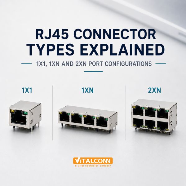
When engineers talk about RJ45 connector types, they usually mean the port configuration first: 1×1, 1×N, or 2×N. A 1x1 RJ45 connector is a single, independent jack. A 1×N part gangs N jacks side by side in one housing — 1×2, 1×4, 1×6, 1×8 — sharing a shield frame and LED position pattern. A 2×N part stacks two of those rows vertically, so a 2×4 gives you eight ports in the depth of one row.
The configuration choice drives PCB panel area, port pitch, airflow, LED routing, and even which switch ASIC you can support. This guide walks through each family, the trade-offs between ganged and stacked housings, and the selection points our application team raises most often with networking customers.
Configuration
Ports
Typical Product
Key Characteristic
1×1
1
Routers, gateways, IPC
Independent housing, free placement
1×2 / 1×4
2–4
Small switches, firewalls
Shared frame, consistent pitch
1×6 / 1×8
6–8
Workgroup switches
Single-row density for front panels
2×2
4
NICs, compact appliances
Two rows, half the width
2×4 / 2×6
8–12
Enterprise line cards
Maximum faceplate density
The 1×1 RJ45 Connector: Maximum Placement Freedom
The single-port jack is the smallest building block and the most flexible. Each 1×1 connector can be placed wherever the board needs it, rotated to face any panel edge, and sourced independently of any other port. In products with one to four Ethernet ports — industrial gateways, security cameras, home routers — designers almost always pick discrete 1×1 jacks because the port count is too low to benefit from ganging.
A 1×1 part also isolates mechanical stress. A user inserting a cable with force on port three of a ganged assembly flexes the whole housing; with discrete jacks the stress stays local. And on mixed-density products where port spacing is set by other connectors (SFP cages, USB, console ports), discrete jacks adapt to irregular pitch that no ganged part matches. For the underlying pinout shared by every one of these jacks, see our RJ45 pinout diagram and wiring guide.
1×N Ganged RJ45 Connectors: The Switch Workhorse
Ganged single-row connectors exist for one reason: dense, uniform port fields. When a switch faceplate needs eight identical RJ45 ports in a row, a 1×8 connector guarantees the port pitch is uniform, the LED positions align with the silkscreen, and the shield frame is one continuous EMI structure instead of eight separate ones. Assembly benefits too: one placement instead of eight, and one shield interconnect instead of many.
The trade-offs are structural. A long ganged housing concentrates insertion force across the whole part, so the mounting legs and their anchor pads must be specified with the full-width assembly in mind — coplanarity tolerance over the length of the housing is the number SMT engineers watch. Individual port replacement is impossible; a damaged port means replacing the whole part. And the fixed pitch of the ganged family must match your facepanel standard, which is usually set by the industry-common port pitch for the switch class you are building.
Ganged parts share one shield frame — verify the shield ground path is continuous across every port segment.
LED options (single, dual-color, or none) are fixed per part family; pick them before panel graphics are frozen.
Long housings need support at both ends and at intermediate legs to control solder-joint stress.
Stacked RJ45 Connector (2×N): Doubling Faceplate Density
A stacked RJ45 connector puts a second row of jacks directly above the first, doubling port count at the same faceplate width. A 2×4 replaces two 1×4 parts with one component and half the panel length; on line cards and NICs where every millimeter of facepanel is revenue, this is the deciding factor.
Stacking changes three engineering conversations. Mechanically, the part is tall, so retention under cable pull and vibration depends on mounting legs at both rows plus the shared housing body. Thermally, two rows of magnetics in one body concentrate heat — for 2×N magnetic jacks, check the temperature-rise data at full PoE load on every port simultaneously, not per port. In layout, routing the upper row's signals under and past the lower row constrains the escape channels, so early floorplanning with the connector's footprint drawing is essential.
Orientation and Entry Options Across RJ45 Connector Types
Independent of port count, RJ45 jacks come in right-angle (side entry, tab up or tab down) and vertical (top entry) orientations. Right-angle with the latch tab down is the common switch faceplate arrangement; tab-up variants exist for compact products where the cable exits upward. Vertical jacks save depth and are used where boards plug into a backplane or where the cable exits the top of an enclosure.
Orientation
Best For
Watch Out For
Right-angle, tab down
Standard switch/router faceplate
Latch interferes with panels below
Right-angle, tab up
Dense 2×N stacking, compact cases
Less common; verify availability
Vertical (top entry)
Backplane modules, depth-limited cases
Cable management above the board
Magnetic Versus Non-Magnetic Within Each Configuration
Every port configuration above exists in both magnetic and non-magnetic variants, and the configuration choice interacts with that one. A 2×N magnetic jack concentrates up to sixteen transformers in one body, so its thermal and crosstalk specifications carry more weight than a 1×1 part's. A 1×N non-magnetic part paired with a discrete magnetics array spreads the heat but consumes routing area exactly where density was the goal. Our magnetic RJ45 vs non-magnetic RJ45 comparison covers the electrical side in detail.
Selection Checklist for Port Configuration
Start from the facepanel standard: total ports, port pitch, and the height available for one or two rows.
Compare total board cost, not connector cost: ganged parts cut placements but add coplanarity and stress risk.
For 2×N magnetic jacks, demand full-port simultaneous thermal data, especially for PoE designs.
Confirm LED style, light-pipe geometry, and legend alignment before the housing is frozen.
Check the footprint drawing against your routing channels — especially upper-row escape in stacked parts.
For products with mixed RJ45 and SFP ports, floorplan both connector families together; see our SFP cage guides for the adjacent constraints.
If you are evaluating connectors for a full design rather than a single port question, our RJ45 connector buying guide and the Ultimate Guide to RJ45 connectors cover shield styles, plating, and manufacturer evaluation criteria.
LED Indicators and Panel Details Across RJ45 Connector Types
Port configuration is the headline decision, but two details ride along with it and cause just as many late-stage changes: LED indication and the panel interface. Most RJ45 connector types are offered with integrated dual-color LEDs (green for link, amber for activity), discrete LED pockets beside each port, or no LED provision at all. Ganged 1×N and stacked 2×N parts with integrated LEDs simplify assembly dramatically, because the operator no longer has to align eight separate light pipes with the front panel cutouts. The trade-off is serviceability: if one LED channel fails on a ganged part, the entire connector is replaced.
When discrete LEDs are used, check the light-pipe alignment tolerance against the front-panel cutout early. We have seen projects where the panel drawing allowed ±0.4 mm on cutout position while the PCB-to-panel stack-up already consumed ±0.3 mm in standoff and hole tolerances, leaving almost nothing for connector placement accuracy. Stacked RJ45 connector parts make this worse, because the upper row of light pipes sits that much farther from the board and amplifies any tilt in the assembly.
Integrated dual-color LEDs: fastest assembly, standard on most ganged parts; verify current-limiting resistors are on the board, not expected inside the jack
Discrete LEDs with light pipes: flexible, but demand a tolerance stack review between PCB, connector, and panel
No LEDs: common on industrial ports where status is reported through management software instead
Panel bezels: many stacked and ganged parts accept an optional front bezel that hides mounting screws and improves EMI contact with the panel
Panel mounting itself deserves a decision, not a default. Ear tabs and integrated studs anchor the connector to the panel so insertion forces never reach the solder joints. This matters most in high port-count panels where a technician plugging stiff Category 6A cables applies real side load. Our recommendation for any panel with more than four ports is simple: choose an RJ45 connector type with panel retention features, and let the PCB carry signals rather than mechanical load.
Frequently Asked Questions (FAQ)
What does 1xN mean in RJ45 connectors?
1×N describes a ganged connector with one row of N RJ45 ports in a shared housing — for example 1×4 for four ports in a row. It contrasts with 1×1 (a single independent jack) and 2×N (two stacked rows). What is a stacked RJ45 connector? A stacked RJ45 connector (2×N) places a second row of jacks directly above the first, doubling port count at the same faceplate width. A 2×4 part provides eight ports in the width normally used by four. When should I use individual 1x1 jacks instead of a ganged connector? Use 1×1 jacks when port count is low (typically under four), when ports must sit at irregular spacing, or when independent mechanical stress isolation and per-port serviceability matter more than placement efficiency. Do ganged RJ45 connectors improve EMI performance? A ganged connector provides one continuous shield frame across all ports, which simplifies shield grounding compared to several separate jacks. Performance still depends on the shield design and grounding of the specific part family.Can 2xN stacked connectors support PoE on all ports at once? Yes, when the part is specified for it. Because the magnetics of both rows share one housing, verify the datasheet's thermal-rise data for all ports powered simultaneously rather than extrapolating single-port ratings.
Need Help Choosing the Right Connector?
VITALCONN Electronics manufactures a full range of RJ45, SFP, USB-C, SIM, and SD card connectors with integrated magnetics, EMI shielding, and PoE support. Contact our application engineers for specifications, samples, and cross-reference support.
View RJ45 Connector Request Samples
Read More




 IPv6 network supported