The Ultimate Guide to RJ45 Connectors (2026)
Jul 07, 2026
The RJ45 connector is the most widely deployed networking connector on Earth. Since its standardization in IEC 60603-7, it has carried data across billions of Ethernet links, from office desktops to factory floors, data centers, and 5G base stations. Despite the rise of fiber optics, the RJ45 remains irreplaceable for the last 100 meters of copper connectivity, and it is evolving to support speeds up to 10 Gigabits per second and power delivery up to 90 watts (PoE++). This guide covers everything an engineer, procurement manager, or product designer needs to know about RJ45 connectors in 2026.
What Is an RJ45 Connector?
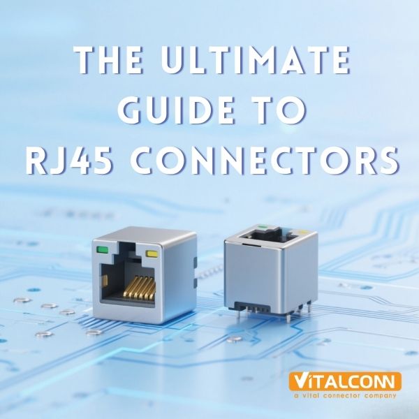
An RJ45 (Registered Jack 45) is an 8-position, 8-contact (8P8C) modular connector used primarily for Ethernet networking. It follows the IEC 60603-7 standard and supports twisted-pair copper cabling (Cat5e through Cat8). The connector consists of a plastic housing with 8 gold-plated contact pins, a spring-loaded latch for retention, and optionally integrated magnetic components (transformers, common-mode chokes) for signal isolation and PoE support.
Brief History
1970s: RJ45 originally developed by Bell Labs for telephone wiring, adapted from the RJ11/RJ14 family
1983: IEEE 802.3 adopted RJ45 for 10Base-T Ethernet at 10 Mbps over Cat3 cable
1995: IEEE 802.3u brought 100Base-TX Fast Ethernet at 100 Mbps over Cat5
1999: IEEE 802.3ab introduced 1000Base-T Gigabit Ethernet at 1 Gbps over Cat5e, requiring all 4 pairs
2006: IEEE 802.3an enabled 10GBase-T at 10 Gbps over Cat6a/Cat7, demanding tighter crosstalk control
2018: IEEE 802.3bt delivered PoE++ Type 3 and Type 4, delivering up to 90W over RJ45
RJ45 Connector Anatomy
Component
Function
Material
Housing
Mechanical protection and latch retention
High-temperature thermoplastic (UL94V-0)
Contact pins (8×)
Electrical connection to cable conductors
Phosphor bronze, gold-plated (flash to 50μ"")
Latch (tab)
Click-in retention in RJ45 jack
Spring steel or integrated plastic
Strain relief (optional)
Prevents cable pull-out damage
Metal or plastic boot
Magnetic module (ICM only)
Signal isolation, PoE, common-mode rejection
Ferrite cores + copper wire
LED indicators (optional)
Link/activity status
Green/Amber SMD LEDs
EMI shield (optional)
Reduces electromagnetic emissions
Stamped metal shell (nickel/copper)
RJ45 Connector Types: Complete Classification
RJ45 connectors come in a wide variety of configurations. Understanding these types is critical for selecting the right part for your design.
By Port Configuration
Type
Description
Typical Application
1×1 (Single Port)
One RJ45 jack in a single housing
Consumer routers, IP cameras, basic NICs
1×N (Ganged Single-Row)
Multiple ports side-by-side in one row
Switches, hubs, patch panels
2×N (Stacked Dual-Row)
Two rows of ports stacked vertically
High-density switches, server motherboards
Combo (RJ45 + USB/SFP)
RJ45 combined with other connector types
Industrial gateways, modular equipment
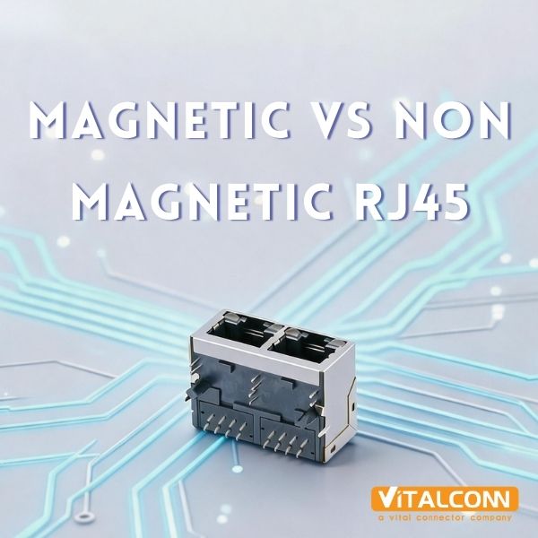
By Magnetic Integration
Type
Magnetics
Use Case
Non-Magnetic RJ45
No internal transformers; external magnetics required on PCB
Cost-sensitive designs with discrete magnetics
ICM (Integrated Connector with Magnetics)
Transformers + common-mode chokes built into connector
Most common; simplifies PCB design, ensures compliance
Magnetic Modular Jack
Full magnetic module with PoE center taps
PoE switches, industrial Ethernet, telecom equipment
💡 Tip: VITALCONN’s ICM RJ45 product line covers 163 models from 10/100Base-T to 10GBase-T, with PoE support from IEEE 802.3af (15.4W) to 802.3bt Type 4 (90W).
By Mounting Type
Mounting
Installation
Best For
DIP (Through-Hole)
Pins soldered through PCB holes
High-reliability, vibration-resistant designs
SMT (Surface Mount)
Pads soldered on PCB surface
High-volume automated production, compact designs
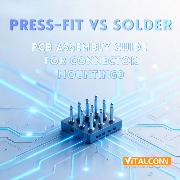
Press-Fit (Compliant Pin)
Pins press into plated PCB holes, no solder
Lead-free processes, rework-free assembly
By Tab Orientation and Shielding
Tab Down (Standard): The most common orientation; tab faces downward when plugged in
Tab Up: Tab faces upward; used when PCB orientation is inverted
Tab Offset: Tab is offset to the side; used in ultra-low-profile designs
Unshielded: No metal shield; suitable for low-speed (10/100M) or minimal EMI environments
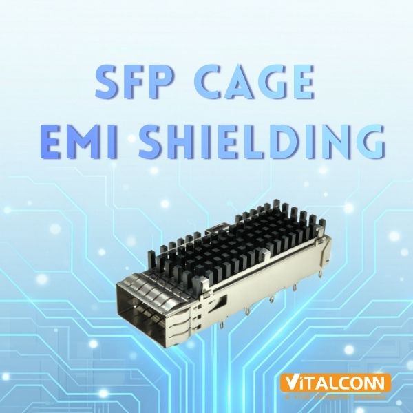
Shielded: Full metal enclosure; required for Gigabit and 10G applications to meet FCC/CISPR emissions limits
Shielded + EMI Gasket: Metal shell plus conductive gasket for 360° grounding; essential for 10GBase-T and high-density switches
Key RJ45 Specifications You Must Know
Speed and Standards
Standard
Speed
Cable
Pairs Used
Max Distance
10Base-T
10 Mbps
Cat3+
2
100m
100Base-TX
100 Mbps
Cat5+
2
100m
1000Base-T
1 Gbps
Cat5e+
4
100m
2.5GBase-T
2.5 Gbps
Cat5e+
4
100m
5GBase-T
5 Gbps
Cat6+
4
100m
10GBase-T
10 Gbps
Cat6a+
4
100m (Cat6a)
PoE (Power over Ethernet) Support
PoE Standard
Type
Max Power (PSE)
Max Power (PD)
Voltage
IEEE 802.3af
Type 1 (PoE)
15.4W
12.95W
44–57V DC
IEEE 802.3at
Type 2 (PoE+)
30W
25.5W
50–57V DC
IEEE 802.3bt
Type 3 (PoE++)
60W
51W
50–57V DC
IEEE 802.3bt
Type 4 (PoE++)
90W
71W
50–57V DC
For PoE applications, the RJ45 connector must have a magnetic module with center-tapped transformers. The center tap carries DC power, so the transformer must handle the full PoE current without saturation. VITALCONN’s PoE-capable ICM RJ45 connectors support up to 90W (Type 4) with thermal management to prevent core saturation at high current.
Gold Plating Thickness
Plating
Thickness
Application
Flash gold
0.05–0.1 μm
Low-cost consumer, low insertion cycles
Standard gold
0.4–0.8 μm (15–30μ"")
General networking equipment
Thick gold
1.0–1.27 μm (40–50μ"")
Industrial, high-reliability, 5,000+ cycles
Isolation Voltage and Operating Temperature
Standard isolation: 1500 VAC RMS minimum (per IEC 60603-7)
Industrial grade: 1500–3000 VAC
High-isolation: 3000–5000 VAC (medical and industrial applications)
Commercial temperature: 0°C to +70°C
Extended temperature: -20°C to +85°C
Industrial temperature: -40°C to +85°C
How to Choose the Right RJ45 Connector: Step-by-Step
Define your speed requirement: Determine the required data rate (10/100M, 1G, 2.5G, 5G, or 10G). This sets the minimum cable category and connector performance class.
Determine PoE requirements: Determine if PoE is needed and what type (af/at/bt Type 3 or 4). This determines whether you need center-tapped magnetics and what current rating is required.
Choose magnetic integration: Choose between ICM (integrated magnetics) or non-magnetic with external magnetics. ICM simplifies design and ensures compliance; external magnetics offer design flexibility.
Select port configuration: Determine single port (1×1), ganged (1×N), or stacked (2×N) based on your port count and PCB space.
Select mounting type: Choose DIP for high reliability and reworkability, SMT for automated high-volume production, or Press-Fit for lead-free, solder-free assembly.
Select gold plating: Choose gold plating thickness based on expected insertion cycles and environmental conditions.
Consider shielding and environment: For Gigabit and above, use shielded connectors with EMI gaskets. For industrial environments, choose -40°C rated parts.
Verify compliance: Ensure the connector is UL recognized and RoHS compliant. For medical devices, check IEC 60601 isolation requirements.
Common RJ45 Design Mistakes (and How to Avoid Them)
Mistake 1: Ignoring PoE Thermal Management
At 90W PoE++, each pair carries nearly 1A of DC current. If the magnetic transformer core is undersized, it will saturate, causing signal degradation and potential fire risk. Always verify that the ICM is rated for the full PoE power level, not just the signal speed.
Mistake 2: Using Unshielded Connectors for 10GBase-T
10GBase-T operates at frequencies up to 500 MHz. Unshielded RJ45 connectors cannot contain these emissions, leading to FCC/CISPR test failures. Always use shielded connectors with 360-degree EMI grounding for 10G applications.
Mistake 3: Mismatched Cable Category and Connector Class
A Cat6a connector on a Cat5e cable (or vice versa) creates an impedance mismatch that causes reflections and signal degradation. Always match the connector performance class to the cable category.
Mistake 4: Overlooking Insertion and Return Loss
Cheap RJ45 connectors often have poor impedance matching, resulting in return loss values that fail IEEE 802.3 limits. Always request S-parameter data from the manufacturer and verify compliance at your target speed.
Mistake 5: Choosing Gold Plating Too Thin for Industrial Use
Flash gold (0.05 μm) may suffice for consumer devices with 50 insertion cycles, but industrial applications requiring 5,000+ cycles need at least 0.4 μm (15 microinches) of gold. Insufficient plating leads to contact oxidation and intermittent connections.
⚠️ Important: At 90W PoE++ (IEEE 802.3bt Type 4), each twisted pair carries approximately 0.96A of DC current. Using an ICM not rated for this current will cause transformer core saturation, signal degradation, and potential fire risk. Always verify the PoE current rating, not just the signal speed rating.
VITALCONN RJ45 Connector Solutions
VITALCONN manufactures 163 ICM RJ45 models and additional non-magnetic RJ45 variants, covering the full range of speeds, port configurations, and mounting types. Our products are ISO 9001 certified and serve customers in networking, industrial automation, and consumer electronics globally.
Key Differentiators
Differentiator
Details
Full Speed Range
10/100Base-T through 10GBase-T, including 2.5G and 5G
Complete PoE Support
IEEE 802.3af (15.4W) through 802.3bt Type 4 (90W)
All Mounting Types
DIP, SMT, and Press-Fit available
Stacked Configurations
2×1 through 2×8 stacked RJ45 with shared or independent magnetics
Customizable Gold Plating
Flash to 50 microinches, tailored to customer requirements
EMI Shielding
Full metal shield with 360° grounding and optional EMI gaskets
Industrial Temperature
-40°C to +85°C rated components for harsh environments
ARP Cross-Reference Platform
26 pin-to-pin replacement records for TE, Molex, Pulse, BelFuse, and more
Featured Products
Stacked Magnetic RJ45 (2×N): Available in 2×1 through 2×8 configurations, supporting 10/100Mbps and 1G with PoE. Cat6 compliant, DIP mounting, with EMI shielding options.
10G PoE++ ICM RJ45: Single-port ICM RJ45 with 10GBase-T support, PoE++ Type 4 (90W), SMT mounting, -40°C to +85°C.
1×N Ganged RJ45: Compact 1×N RJ45 for high-density switches with shared magnetics module and LED indicators.
ARP: Alternative Replacement Platform
VITALCONN’s ARP platform provides 123 pin-to-pin replacement records across 5 product categories. For RJ45 specifically, we offer 26 cross-reference replacements covering 11 different competitor brands, including Pulse Electronics, BelFuse, TE Connectivity, Molex, Amphenol, and more. This means you can often replace an EOL or shortage-affected part with a VITALCONN equivalent without redesigning your PCB.
💡 Tip: ARP cross-reference replacements offer 30–40% cost reduction vs. original parts, 2–4 week lead time (vs. 12–24 weeks for many competitors), and pin-to-pin mechanical and electrical compatibility. Contact sales@vitalconn.com with your current part number for a match.
Frequently Asked Questions (FAQ)
What does RJ45 stand for?
RJ45 stands for Registered Jack 45. It is an 8-position, 8-contact (8P8C) modular connector standardized under IEC 60603-7. Despite the “registered jack” name, it is now primarily used for Ethernet networking rather than telephone wiring.
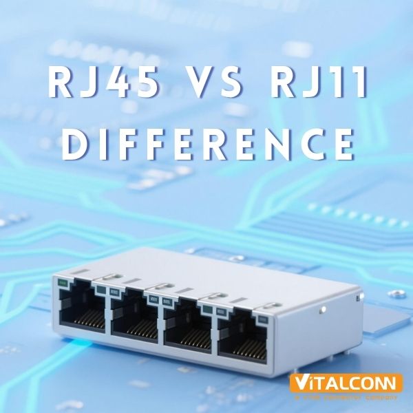
What is the difference between RJ45 and RJ11?
RJ45 has 8 contacts (8P8C) and is used for Ethernet; RJ11 has 6 positions with 2 or 4 contacts (6P2C/6P4C) and is used for telephone lines. RJ45 is physically larger than RJ11. An RJ11 plug can fit into an RJ45 jack, but this is not recommended as it can damage the contacts.
Do I need a magnetic (ICM) RJ45 or a non-magnetic one?
If your PCB has discrete magnetics already laid out, you can use a non-magnetic RJ45. However, most modern designs use ICM because it simplifies PCB layout, ensures IEEE compliance, and provides better signal integrity. ICM is essentially mandatory for PoE applications because the center-tapped transformer is needed to inject DC power.
Can RJ45 support 10 Gigabit Ethernet?
Yes. 10GBase-T (IEEE 802.3an) operates over RJ45 connectors with Cat6a or Cat7 cabling at distances up to 100 meters. However, 10G requires shielded connectors with tight impedance control (100 ± 15 ohms) and low crosstalk. VITALCONN offers 10G-rated ICM RJ45 connectors with full metal shielding and EMI gaskets.
What PoE power levels can RJ45 handle?
RJ45 connectors with appropriate magnetics can support the full range of PoE standards: IEEE 802.3af (15.4W), 802.3at (30W), and 802.3bt Type 3 (60W) and Type 4 (90W). At 90W, each twisted pair carries approximately 0.96A of DC current, requiring magnetics designed to handle this current without core saturation.
What is the maximum number of insertion cycles for RJ45?
Standard RJ45 connectors are rated for 750 insertion cycles minimum (per IEC 60603-7). Industrial-grade connectors with thicker gold plating (30–50 microinches) can achieve 5,000+ cycles. VITALCONN offers gold plating up to 50 microinches for high-cycle applications.
How do I know if a VITALCONN RJ45 can replace my current part?
VITALCONN’s ARP (Alternative Replacement Platform) provides 26 pin-to-pin RJ45 cross-reference records covering Pulse, BelFuse, TE, Molex, Amphenol, and 6 other brands. Contact sales@vitalconn.com with your current part number, and we will identify the equivalent VITALCONN model, typically with 30–40% cost savings and faster lead times.
Ready to Find the Right RJ45 Connector?
Explore VITALCONN’s 163+ ICM RJ45 models—10/100M to 10G, PoE to 90W, pin-to-pin compatible with Pulse, BelFuse, TE, and Molex—or request free samples and ARP cross-reference support for your next project.
Explore RJ45 Connectors Request Samples
Read More


 IPv6 network supported