The Ultimate Guide to LAN Transformer Modules (2026)
Jul 22, 2026
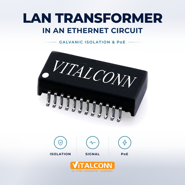
A LAN transformer module is the unsung hero of every Ethernet connection, silently isolating signals, suppressing noise, and ensuring reliable data transmission from 10Mbps to 10Gbps. As a manufacturer of 39 LAN transformer models with isolation ratings up to 6kV, VITALCONN Electronics has spent 14 years perfecting the design and production of these critical components. This guide shares our manufacturing expertise to help you understand LAN transformer modules from the inside out.
Whether you are designing a 10 Gigabit Ethernet switch, a Power over Ethernet (PoE++) camera, or an industrial gateway, the LAN transformer module you select directly impacts signal integrity, EMI compliance, and system reliability. This comprehensive guide covers everything from basic working principles to advanced selection criteria.
What You Will Learn1) LAN transformer module fundamentals and working principles 2) Complete type classification (discrete vs integrated, SMT vs DIP) 3) Key specifications (isolation, insertion loss, return loss, crosstalk) 4) PoE/PoE+/PoE++ magnetics requirements 5) Common mode choke and EMI suppression 6) How to choose the right LAN transformer module 7) Common design mistakes 8) VITALCONN's 39-model product line
What Is a LAN Transformer Module? A Manufacturer's Definition
A LAN transformer module is a magnetic component that provides signal isolation and impedance matching between a PHY (Physical Layer) chip and the Ethernet cable (twisted pair). It consists of multiple transformers and common mode chokes integrated into a single package, typically 6 to 88 pins. The LAN transformer module ensures that differential Ethernet signals are transmitted with minimal distortion while blocking common mode noise and providing galvanic isolation.
Core Components Inside a LAN Transformer Module
Isolation Transformer: Transforms the differential signal voltage level and provides galvanic isolation (typically 1500VAC minimum).
Common Mode Choke (CMC): Suppresses common mode EMI noise on the twisted pair, preventing radiation from the cable.
Center Tap (CT): Provides DC power injection/extraction for PoE applications (IEEE 802.3af/at/bt).
Impedance Matching: Matches the 100-ohm impedance of twisted pair cable to the PHY output impedance.
Auto Transformer (optional): Provides a defined return path for signal current, reducing EMI emissions.
Why Ethernet Needs a LAN Transformer Module
Without a LAN transformer module, a PHY chip cannot drive an Ethernet cable directly. The module provides three essential functions that cannot be integrated into the PHY chip:
Galvanic isolation: IEEE 802.3 requires 1500VAC isolation between PHY and cable for safety and surge protection.
Common mode noise rejection: CMC blocks noise that would otherwise radiate from the cable, failing FCC/CISPR EMI limits.
Impedance matching: The module matches the PHY's output to 100 ohm differential impedance, minimizing signal reflections.
How a LAN Transformer Module Works: Signal Path Explained
Understanding the LAN transformer module's working principle requires tracing the signal path from PHY to cable. Here is what happens when a data packet is transmitted:
Signal Path: TX Direction (PHY to Cable)
Step 1: PHY generates a differential voltage signal on TX+ and TX- pins.
Step 2: Signal enters the LAN transformer module's primary winding (PHY side).
Step 3: Transformer couples the signal to the secondary winding (cable side) via magnetic flux.
Step 4: Galvanic isolation is maintained between primary and secondary (no DC path).
Step 5: Signal passes through the common mode choke, which attenuates common mode noise.
Step 6: Differential signal exits to the RJ45 jack and onto the twisted pair cable.
PoE Power Injection via Center Tap
In PoE applications, DC power (48V) is injected through the transformer's center tap. The LAN transformer module must be designed to handle the DC current without saturating the core. VITALCONN's PoE++ magnetics are rated for 600mA per channel (IEEE 802.3bt Type 4, 90W), with gapped cores that prevent saturation under DC bias.
LAN Transformer Module Types: Complete Classification
By Integration Level
Type
Description
Advantages
Best For
Discrete Magnetics
Standalone transformer module, separate from RJ45
Lower cost, flexible PCB layout
Space-constrained designs
Integrated (ICM)
Transformer built into RJ45 connector (ICM RJ45)
Fewer components, simpler assembly
Most common Ethernet devices
Phy-Side Magnetics
Transformers on PHY side, between PHY and connector
Shorter high-speed traces
High-density switch/router designs
By Speed Rating
Speed
Frequency
Turns Ratio
VITALCONN Models
10/100Base-TX
up to 100MHz
1CT:1CT or 1:1
TG series (6-48 pin)
1000Base-T (Gigabit)
up to 100MHz, 4 pairs
1CT:1CT
TH series (16-48 pin)
2.5G/5GBase-T
up to 250/500MHz
1CT:1CT
TK series (high-freq)
10GBase-T
up to 500MHz
1CT:1CT
TK-10G series
By Mounting Type
Mounting
Assembly
Advantages
VITALCONN Series
SMT
Reflow soldering
High-speed automated assembly
TG-SMT, TH-SMT
DIP
Through-hole wave soldering
Mechanical robustness, lower cost
TG-DIP, TH-DIP
Key Specifications: What to Look for in a LAN Transformer Module
Selecting a LAN transformer module requires understanding several critical specifications. VITALCONN tests every parameter on 100% of production units.
Electrical Specifications
Parameter
Typical Spec
Why It Matters
Test Method
Isolation Voltage
1500-5000 VAC
Safety compliance, surge protection
Hi-Pot test, 1 minute
Insertion Loss
<1.0dB @ 100MHz (1G)
Signal attenuation; lower = better
Network analyzer, S21
Return Loss
>18dB @ 100MHz (1G)
Signal reflection; higher = better
Network analyzer, S11
Crosstalk (NEXT)
>40dB @ 100MHz
Inter-channel interference
Network analyzer, near-end
Common Mode Rejection
>40dB @ 100MHz
EMI suppression capability
CMRR measurement
DC Resistance (CT)
<1.0 ohm per winding
PoE power loss; lower = better
DC milliohmmeter
Hi-Pot Leakage
<2mA at 1500VAC
Safety isolation verification
Hi-Pot tester
Manufacturer's Real Data: Insertion LossVITALCONN's 10G LAN transformer modules achieve <0.8dB insertion loss at 500MHz, verified by Keysight network analyzer. This is 20% better than the IEEE 802.3ae maximum of 1.0dB, meaning less signal attenuation and longer achievable cable distances.
Environmental Specifications
Parameter
VITALCONN Standard
Industry Standard
Notes
Operating Temperature
-40℃ to +85℃
-0℃ to +70℃ (commercial)
Industrial grade available
Storage Temperature
-40℃ to +125℃
-25℃ to +85℃
Extended storage range
Soldering Heat
260℃ for 10s (reflow)
260℃ for 10s (JEDEC)
Lead-free compatible
Humidity
85% RH, 85℃, 168h
85% RH, 85℃, 168h
THB (Temp-Humidity-Bias) test
PoE Magnetics: How a LAN Transformer Module Handles 90W
Power over Ethernet (PoE) places unique demands on the LAN transformer module. The center tap must carry DC current without saturating the transformer core. Here is how VITALCONN designs magnetics for each PoE standard:
PoE Standard
Power
Current per CT
Design Consideration
IEEE 802.3af (PoE)
15.4W (max)
350mA
Standard core, no special gap needed
IEEE 802.3at (PoE+)
30W (max)
600mA
Gapped core to prevent saturation
IEEE 802.3bt Type 3
60W (max)
600mA per pair
Dual-pair injection, larger core
IEEE 802.3bt Type 4
90W (max)
960mA per pair
High-current winding, thermal management
How to Choose the Right LAN Transformer Module: 6-Step Guide
Step 1 - Speed: Determine required speed: 10/100, 1G, 2.5G, 5G, or 10G. Higher speeds require wider bandwidth magnetics.
Step 2 - PoE: Check PoE requirements: af (15W), at (30W), bt Type 3 (60W), bt Type 4 (90W). Higher power needs gapped cores and higher-current CT windings.
Step 3 - Isolation: Verify isolation voltage: 1500VAC minimum for commercial, 5000VAC for industrial/medical.
Step 4 - Signal: Check insertion loss and return loss at your operating frequency. <1.0dB IL and >18dB RL for 1G.
Step 5 - Mounting: SMT for high-volume automated assembly, DIP for mechanical robustness.
Step 6 - Environment: Verify temperature range: -40℃ to +85℃ for industrial, -0℃ to +70℃ for commercial.
Common LAN Transformer Module Design Mistakes
Mistake 1: Ignoring DC Saturation in PoE++ Applications
At 960mA (PoE++ Type 4), a standard transformer core saturates, causing signal distortion and EMI failures. Always specify gapped cores for PoE applications above 30W.
Mistake 2: Mismatched Turns Ratio
Using a 1:2 turns ratio when the PHY expects 1:1 causes impedance mismatch, resulting in signal reflections and link errors. Always verify the turns ratio matches your PHY's requirements (typically 1CT:1CT for most Ethernet PHYs).
Mistake 3: Insufficient Isolation for Industrial Applications
Commercial-grade LAN transformer modules with 1500VAC isolation may fail in industrial environments with high surge levels. Specify 2500-5000VAC isolation for industrial and medical applications.
VITALCONN LAN Transformer Module Solutions: 39 Models
VITALCONN manufactures 39 LAN transformer module models covering speeds from 10Mbps to 10Gbps, with PoE support up to 90W (IEEE 802.3bt Type 4):
Series
Speed
PoE Support
Pin Count
Isolation
TG Series
10/100Base-TX
af/at
6-24
1500-3000 VAC
TH Series
1000Base-T (1G)
af/at/bt
16-48
1500-5000 VAC
TK Series
2.5G/5G/10GBase-T
at/bt
16-48
1500-3000 VAC
TT Series
10/100 + PoE+
at (30W)
6-24
1500-3000 VAC
Frequently Asked Questions (FAQ)
What is a LAN transformer module?
A LAN transformer module is a magnetic component that provides signal isolation, impedance matching, and common mode noise suppression between an Ethernet PHY chip and the network cable. It typically contains isolation transformers, common mode chokes, and center-tap connections for PoE power injection.
What isolation voltage do I need for a LAN transformer module?
IEEE 802.3 requires minimum 1500VAC isolation. For industrial applications, 2500-3000VAC is recommended. For medical devices, 5000VAC may be required per IEC 60601. VITALCONN offers 1500-5000VAC options across 39 models.
Can a LAN transformer module support PoE++ 90W?
Yes, but it requires a gapped core design to prevent DC saturation at 960mA. VITALCONN's PoE++ magnetics use gapped ferrite cores and high-current center-tap windings, validated at 960mA continuous DC bias without signal degradation.
What is the difference between integrated (ICM) and discrete LAN transformer modules?
Integrated magnetics (ICM) combine the transformer and RJ45 connector into one package, simplifying assembly. Discrete magnetics are separate components, offering more layout flexibility but requiring more PCB space. Most modern designs use ICM for space efficiency.
How do I test a LAN transformer module?
Key tests include: insertion loss (S21) and return loss (S11) via network analyzer, Hi-Pot isolation test, DC resistance measurement, and crosstalk (NEXT) measurement. VITALCONN performs 100% electrical testing on every unit.
What causes LAN transformer module failures?
Common causes include: DC core saturation in PoE applications, insufficient isolation voltage for the environment, solder joint cracks from thermal cycling, and EMI failures from poor PCB layout. Proper specification and 100% testing prevent most failures.
Do I need a LAN transformer module for 10G Ethernet?
Yes, all Ethernet connections require magnetics for isolation and noise suppression. 10GBase-T LAN transformer modules must support up to 500MHz bandwidth with <1.0dB insertion loss. VITALCONN's TK-10G series meets these requirements.
What is the operating temperature range of VITALCONN LAN transformer modules?
All VITALCONN LAN transformer modules are rated for -40℃ to +85℃, meeting industrial temperature requirements. This is wider than commercial-grade modules (-0℃ to +70℃), making them suitable for outdoor and industrial applications.
Need LAN Transformer Modules with Verified Performance Data?
Request datasheets and free samples from VITALCONN's 39 LAN transformer models.
Explore LAN Transformers Request Samples
Read More





 IPv6 network supported