LAN Transformer Selection Guide: Turns Ratio, Isolation and CMRR
Oct 16, 2026
Start LAN Transformer Selection With the PHY, Not the Part Number
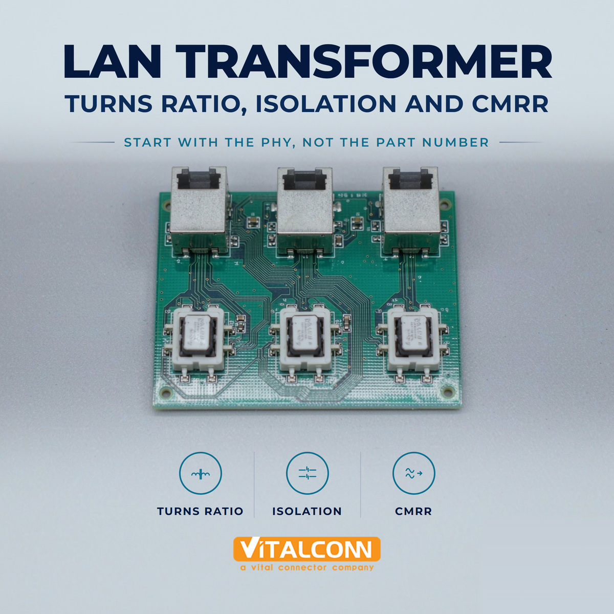
LAN transformer selection works best in one direction: from the PHY's requirements outward to the component. Picked the other way round, teams end up with a favourite part number and a portfolio of boards that each behave slightly differently at the margins. The PHY datasheet defines what the magnetic interface has to provide, and almost every disagreement about whether a given transformer will work can be settled there.
In practice four parameters decide almost everything, and they are interdependent rather than independent: turns ratio, open circuit inductance, isolation rating and common-mode behaviour. Reading any one of them without the other three is how datasheet comparisons go wrong. If you need to refresh what the magnetic block actually does between PHY and cable before reading further, our background piece on what a LAN transformer does sets the scene.
Turns Ratio: Matching the PHY and the Line
Most Ethernet magnetic channels are specified as a centre-tapped one-to-one ratio on each differential pair, because the PHY-side driver and the line are designed to be impedance matched through that unity relationship. Where a PHY deviates, it will say so explicitly, sometimes recommending a different ratio to accommodate a particular drive level or receiver sensitivity. Deviating from the PHY's stated recommendation without a reason is a redesign risk with little upside.
Parameter
What it controls
Typical specification approach
Common mistake
Turns ratio
Signal amplitude ratio between PHY and line
Per differential pair, centre tapped
Choosing away from the PHY recommendation without reason
Open circuit inductance
Low-frequency response and droop
Minimum value at a stated DC bias
Comparing figures measured under different test conditions
Isolation rating
Safety withstand between port and system
Withstand voltage for a stated duration
Equating test voltage with continuous working voltage
CMRR / common-mode rejection
Susceptibility to common-mode noise
Attenuation in dB versus frequency
Comparing dB values quoted at different frequencies
Also check how the centre taps are presented. In a discrete part they are separate pins with their own routing and termination requirements, and that termination, not the transformer core, frequently explains common-mode behaviour differences between two otherwise similar designs.
Why Open Circuit Inductance Sets the Low-Frequency Limit
Open circuit inductance, usually abbreviated OCL, describes how much magnetising inductance the winding presents, and therefore how the low-frequency end of the signal is treated. Too little and the waveform droops, which shows up as baseline wander rather than as obvious noise. Datasheets commonly quote a minimum figure in the hundreds of microhenries measured under a defined DC bias current.
The test condition is the part people skip. An inductance figure quoted without the bias current used to measure it is not comparable across datasheets, because magnetising inductance falls as bias current rises. When comparing candidates, put the test conditions side by side first and only then compare the numbers. This single habit resolves more apparent contradictions than any other comparison technique.
Isolation: What the Voltage Rating Does and Does Not Cover
Galvanic isolation is the reason the transformer exists at all in a twisted-pair port, separating the system ground from whatever is connected to the far end of possibly hundreds of metres of cable. The headline number is a withstand rating: the voltage the part is tested to survive for a defined duration, commonly quoted in the region of 1500 Vrms for Ethernet ports. That number is a test result, not an operating condition.
Treat the withstand figure as type-test evidence, not as a voltage the design may apply continuously
Confirm the working voltage expectation for your application separately from the withstand rating
Remember that clearance and creepage on your own board matter as much as the component rating
Keep the isolation boundary clean in layout, including any circuitry that crosses it
Isolation also carries a system-level implication for the products you ship. If the product is sold into a market requiring a specific safety file, the transformer's rating has to sit inside that file, which means choosing the part early enough that certification is not the surprise at the end of the project.
LAN Transformer CMRR and Common-Mode Noise
LAN transformer CMRR describes how effectively the magnetic channel rejects signals that appear identically on both conductors of the pair, as opposed to the differential signal carrying data. The common-mode choke integrated into the magnetic assembly does most of this work, presenting high impedance to common-mode current while leaving differential signals largely untouched.
The reason to care is practical rather than theoretical. Common-mode energy arrives from switching supplies, from adjacent pairs, from ground potential differences on long runs and from external interference, and the receiver sees whatever the transformer fails to reject. Because rejection is frequency dependent, figures are meaningful only when compared at the same frequency, and the range that matters is the one occupied by the signalling you are running.
Where EMI behaviour becomes the binding constraint, treat the magnetic choice and the enclosure return path as one problem. Our shielded vs unshielded RJ45 discussion covers the connector side of that boundary, and the two decisions should be made in the same review rather than in separate meetings.
Insertion Loss, Return Loss and the Signal Budget
Beyond the headline parameters, the channel has a budget. Insertion loss consumes signal amplitude, return loss reflects how well the impedance stays matched through the magnetics, and crosstalk between channels sets how much energy leaks between adjacent ports. Each is specified across frequency on a competent datasheet, and each should be added to the contributions from your board traces, connector and cable before concluding there is margin.
Compare like with like here as well. Two datasheets may quote different frequency ranges or different reference impedances, and a figure that looks better in one column often turns out to be quoted more favourably rather than genuinely superior. Where a parameter is missing from a datasheet entirely, treat that as information.
PoE: DC Bias Changes the Selection Entirely
Once power is carried on the same pairs, the transformer sees DC current through its windings and centre taps. That bias shifts magnetising inductance downward, which affects exactly the low-frequency behaviour discussed above, and the effect grows with delivered power. A magnetic channel that measures comfortably at low power can behave differently once the design supplies the higher classes defined for modern PoE implementations.
So specify the magnetic channel for the highest PoE class the product will actually deliver, not the one in the first configuration shipped. Check the bias current the inductance figure assumes matches your delivered power, verify the centre tap current capability, and remember that current ultimately flows through contacts as well, which is why the RJ45 gold plating choice and the magnetics choice belong in the same specification. Our RJ45 connector selection material covers how data rate class and port construction interact on that side of the boundary.
Discrete Transformer or Integrated Magnetic RJ45
The structural question is whether the magnetics sit on the board as a discrete component or inside the connector as part of an integrated RJ45 jack. Integrated parts save board area and simplify routing, which is why they dominate switching equipment. Discrete transformers give more freedom over the magnetic parameters themselves and can be placed where routing and thermal conditions are more favourable.
Consideration
Integrated magnetic RJ45
Discrete LAN transformer
Board area
Lower total footprint
More area required
Parameter freedom
Limited to the jack family offered
Wider choice of magnetic characteristics
Routing simplicity
Pairs terminate at one location
Additional routing between connector and magnetics
Thermal placement
Fixed at panel
Can be positioned for better conditions
Replacement strategy
Change the jack assembly
Change one component
There is no universal answer, and the decision is usually made at the product architecture level rather than during detail design. What matters for this article is that the Ethernet transformer parameters above still have to be read and checked regardless of which structure is chosen, because integration changes the packaging, not the physics.
LAN Transformer Selection Checklist
Begin with the PHY datasheet recommendation for turns ratio and terminations
Compare open circuit inductance only against figures measured at the same DC bias condition
Separate the withstand rating from the working voltage requirement in your specification
Compare common-mode rejection at the frequencies your signalling actually occupies
Specify the magnetic channel for the highest PoE class the product will deliver, not the first one
Add magnetic, trace, connector and cable contributions before deciding there is margin
VITALCONN supplies both discrete LAN transformer parts and integrated magnetics inside RJ45 assemblies, and publishes dimensional drawings so that footprint decisions can be checked before layout rather than after it. If you are working from a reference design, send the PHY part number and the target PoE class and the shortlist usually becomes obvious quickly. Our RJ45 pinout and wiring guide covers the connector side of the interface for teams verifying their pin mapping at the same time.
Frequently Asked Questions (FAQ)
What is the most common LAN transformer selection mistake?
Comparing datasheet figures quoted under different test conditions. Open circuit inductance depends on the DC bias used when measuring it, and common-mode rejection depends on frequency, so numbers that appear directly comparable often are not.
How does PoE affect the transformer choice?
Delivered power flows as DC bias through the windings, reducing magnetising inductance and stressing the centre tap current capability. Specify the magnetic channel for the highest PoE class the product will ever deliver, rather than the configuration shipping first.
Is a higher isolation rating always better?
Higher withstand ratings are useful, but they do not replace a clean isolation boundary in layout. Treat the rating as type-test evidence and confirm separately what continuous working voltage your application actually needs.
Should I use a discrete transformer or integrated magnetics?
It is largely an architecture decision. Integrated parts save board area and simplify routing, while discrete transformers offer more freedom over magnetic parameters and better thermal placement. The same electrical parameters must be checked in either case.
How much insertion loss budget should I allow for the magnetics?
Take the figure from the datasheet across the relevant frequency range and add it to your board, connector and cable contributions, comparing against the total the PHY and standard allow. Avoid assuming a generic allowance without checking the specific part.
Why does CMRR matter more in industrial installations?
Industrial environments add ground potential differences, motor drives and long cable runs, all of which inject common-mode energy. Higher common-mode rejection at the frequencies your link uses keeps that energy away from the receiver input.
Need the Right LAN Transformer for Your PHY?
Get samples, full datasheets, and FAE support from VITALCONN's LAN transformer product line.
Explore LAN Transformers Request Samples
Read More



 IPv6 network supported