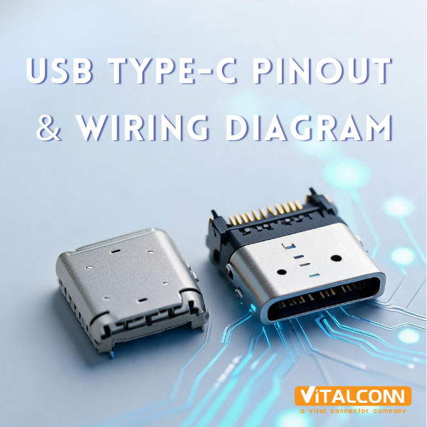
USB Type-C Pinout & Wiring Diagram: 24-Pin Explained (2026)
Jul 20, 2026
The USB C pinout defines how each of the 24 pins in a USB Type-C connector functions, carrying data, power, and configuration signals. Whether you are designing a PCB layout, troubleshooting a charging issue, or selecting connectors for a new product, understanding the USB C pinout is essential. This guide breaks down every pin, its function, and practical wiring considerations, based on VITALCONN's experience as a manufacturer of 93+ USB-C connector models.
The USB C pinout is symmetrical by design, meaning the connector works regardless of insertion orientation. This is achieved through mirrored pin pairs on the receptacle. Let us examine each pin group in detail.
USB C Pinout: Complete 24-Pin Reference Table
The USB C pinout consists of 24 pins arranged in a specific pattern. Here is the complete pin assignment for a full-featured 24-pin USB Type-C receptacle:
Pin
Name
Type
Function
Notes
A1
GND
Ground
Power ground return
Connected to shield
A2
TX1+
Signal
SuperSpeed TX lane 1 positive
USB 3.x/4 transmit+
A3
TX1-
Signal
SuperSpeed TX lane 1 negative
USB 3.x/4 transmit-
A4
VBUS
Power
Bus power (5V-48V)
Up to 5A (PD 3.1)
A5
CC1
Config
Configuration Channel 1
Orientation detection, PD communication
A6
D+
Signal
USB 2.0 data positive
Backward compatibility
A7
D-
Signal
USB 2.0 data negative
Backward compatibility
A8
SBU1
AUX
Sideband Use 1
Alt Mode auxiliary (DP, analog audio)
A9
VBUS
Power
Bus power (5V-48V)
Parallel with A4
A10
RX2-
Signal
SuperSpeed RX lane 2 negative
USB 3.x/4 receive-
A11
RX2+
Signal
SuperSpeed RX lane 2 positive
USB 3.x/4 receive+
A12
GND
Ground
Power ground return
Connected to shield
B1-B12
Mirrored
Mirror
Mirror of A1-A12
Enables reversible insertion
Key Insight: Pin MirroringPins B1-B12 are exact mirrors of A1-A12. This means TX1+ on A2 becomes TX1+ on B12 when flipped. The CC pin that makes contact determines orientation, and the host switches TX/RX lanes accordingly. This is why USB C pinout enables true reversibility.
USB C Pinout: Functional Pin Groups Explained
Power Pins: VBUS and GND
In the USB C pinout, VBUS pins (A4, A9, B4, B9) carry bus power from 5V to 48V, supporting up to 5A (PD 3.1, 240W). GND pins (A1, A12, B1, B12) provide the return path and are connected to the connector shield. The four VBUS pins are paralleled internally to distribute current and reduce contact resistance, which is critical at 5A loads.
VITALCONN's 24-pin USB-C connectors use 0.25mm-thick phosphor bronze for VBUS and GND contacts, achieving <20mΩ contact resistance, 33% below the USB-IF maximum of 30mΩ.
Configuration Channel (CC) Pins
CC1 (A5) and CC2 (B5) are the most important pins in the USB C pinout for functionality. They serve three critical functions:
Orientation: Detecting cable orientation and direction (which side is plugged in)
Current Advertisement: Determining current capacity (default 500mA, 1.5A, or 3A) via pull-up resistor value
PD Communication: Carrying USB Power Delivery (PD) messages via BMC (Biphase Mark Coding) modulation
When a plug is inserted, one CC pin contacts the cable's CC wire while the other contacts VCONN (used to power electronically marked cables). The host reads the voltage on CC to determine orientation and current capability.
SuperSpeed Data Lanes: TX and RX
The USB C pinout includes four high-speed differential pairs for SuperSpeed data:
Lane 1 TX: TX1+/TX1- (A2/A3): Transmit lane 1
Lane 1 RX: RX1+/RX1- (B11/B10): Receive lane 1
Lane 2 TX: TX2+/TX2- (B2/B3): Transmit lane 2
Lane 2 RX: RX2+/RX2- (A11/A10): Receive lane 2
These lanes support USB 3.0 (5Gbps), USB 3.1 (10Gbps), USB 3.2 (20Gbps), and USB4 (40Gbps). Only one TX/RX pair pair is active at a time, determined by plug orientation. In USB4 v2.0, all four pairs can be used simultaneously for 80Gbps.
USB 2.0 Data Pins: D+ and D-
D+ (A6/B6) and D- (A7/B7) provide USB 2.0 compatibility at 480Mbps. These pins exist on both sides of the USB C pinout (mirrored), so only one set is active. They ensure backward compatibility with legacy USB devices and are the only data pins present on 12-pin and 14-pin connectors.
Sideband Use (SBU) Pins
SBU1 (A8) and SBU2 (B8) are auxiliary pins used in Alternate Modes. In DisplayPort Alt Mode, SBU carries the AUX channel for EDID and link training. In analog audio mode, SBU carries microphone and speaker signals. Only one SBU pin is active depending on orientation.
USB C Pinout Wiring Guide: Practical PCB Layout Tips
Designing a PCB with USB Type-C requires careful attention to the USB C pinout layout. Here are practical recommendations from VITALCONN's engineering team:
Power Routing: Route VBUS and GND with 1oz copper, minimum 0.3mm trace width for 3A, 0.5mm for 5A. Use copper pours for GND.
High-Speed: Route TX/RX differential pairs with 90-ohm differential impedance, 0.15mm trace width, 0.1mm spacing. Keep length mismatch <5 mils.
CC Pins: Place CC1 and CC2 near the connector edge, route to PD controller with 0.15mm traces. Add 0.1μF decoupling cap.
USB 2.0: Route D+/D- as 45-ohm differential pair. Add ESD protection diodes within 3mm of connector pins.
Grounding: Use a solid GND plane directly under the connector. Stitch vias around the connector perimeter for shielding.
ESD Protection: Place TVS diodes on VBUS, CC, D+/D-, and SBU pins. Use components rated for the maximum PD voltage (48V for PD 3.1).
Manufacturer's Tip: 12-Pin vs 24-Pin PCB LayoutFor 12-pin USB-C connectors, only VBUS (A4/A9/B4/B9), GND, CC, D+/D-, and SBU pins are present. The TX/RX lanes are absent, so you only need USB 2.0 routing. This simplifies PCB design and reduces cost, but limits data speed to 480Mbps and eliminates Alt Mode support.
USB C Pinout and Alternate Modes
The USB C pinout supports Alternate Modes, where certain pins are repurposed for non-USB protocols. The CC pins negotiate which Alt Mode to enter during connection:
Alt Mode
Pins Repurposed
Max Resolution
Common Use
DisplayPort
TX/RX lanes + SBU
8K@60Hz (DP 2.0)
External monitors, docks
HDMI
TX/RX lanes (via DP++ bridge)
4K@60Hz
TVs, projectors
Thunderbolt 3/4
TX/RX lanes + SBU
8K@60Hz, 40Gbps data
High-performance docks, eGPU
Analog Audio
D+/D-, SBU, SBU2
Analog audio
Headphone adapter (legacy)
PCIe (USB4)
TX/RX lanes
32Gbps PCIe
External NVMe SSDs
For a comprehensive overview of USB-C connector types, see our Ultimate Guide to USB Type-C Connectors.
Frequently Asked Questions (FAQ)
How many pins does a USB Type-C connector have?
A full-featured USB Type-C connector has 24 pins (12 on each side). However, 12-pin, 14-pin, and 16-pin variants exist for cost-sensitive applications. The USB C pinout is symmetrical, with pins B1-B12 mirroring A1-A12 for reversible insertion.
What is the function of CC pins in USB C pinout?
CC1 and CC2 pins serve three functions: detecting plug orientation, advertising current capacity (500mA/1.5A/3A via pull-up resistor), and carrying USB Power Delivery (PD) messages. CC pins are the most critical pins in the USB C pinout for protocol negotiation.
Can I use a 12-pin USB-C connector for USB 3.0?
No. 12-pin USB-C connectors only have USB 2.0 (D+/D-) data pins. USB 3.0 requires the TX/RX SuperSpeed lanes, which are only present on 16-pin and 24-pin connectors. Check the USB C pinout before selecting a connector.
What voltage does VBUS carry in USB C pinout?
VBUS carries 5V by default, but with USB Power Delivery, it can range from 5V to 48V (PD 3.1). The maximum current is 5A, supporting up to 240W. VBUS pins (A4, A9, B4, B9) are paralleled to distribute current.
Are USB C pinout and USB A pinout compatible?
No, they have completely different pinouts. USB Type-A has 4 pins (VBUS, D+, D-, GND), while USB Type-C has 24 pins. However, USB-C is backward compatible with USB 2.0 through the D+/D- pins in its pinout. An adapter cable is needed for physical compatibility.
Need USB-C Connectors with Verified Pinout Specifications?
Get technical datasheets and free samples from VITALCONN's 93 USB-C connector models.
Explore USB-C Request Samples
Read More



 IPv6 network supported