Card Socket Connector Types: SIM, SD, TF, Smart Card & Selection Guide
May 22, 2026
Every electronic device that reads a removable card — your smartphone reading a SIM, your camera writing to an SD card, your payment terminal authenticating a chip card — relies on one humble component: the card socket connector. It's the physical gatekeeper that makes (and breaks) the connection between the card and the host system.
Choose the wrong card socket, and you might face intermittent card detection failures, pins that wear out after a few hundred insertions, or a design that can't fit inside your enclosure. Choose the right one, and it becomes a component you never have to think about again.
In this guide, we'll walk through every major type of card socket connector — SIM, SD, microSD, TF, Smart Card, and Card Edge — along with their insertion mechanisms, pinout configurations, and the key parameters that should drive your selection.
What Is a Card Socket Connector?
A card socket connector is an electromechanical receptacle mounted on a printed circuit board (PCB) that provides a detachable interface between a removable memory or identity card and the host system. The connector's core functions are:
Mechanical retention — Holds the card securely during operation, preventing disconnection due to vibration, shock, or cable handling
Electrical contact — Spring-loaded metal pins (contacts) press against the card's gold-plated pads, establishing reliable signal and power connections
Card detection — A dedicated switch or pin notifies the host when a card is inserted or removed, triggering firmware-level responses
Write protection sensing — On SD and some Smart Card connectors, a mechanical switch detects the card's write-protect tab position
ESD grounding — The metal shell or grounding contacts safely discharge electrostatic events during card insertion
Key point: A card socket is not just a holder. It is a precision electromechanical component where tenth-of-a-millimeter tolerances in contact force, alignment, and plating directly determine your product's card-reading reliability.
Types of Card Socket Connectors
Card sockets are not one-size-fits-all. Each card format has its own physical dimensions, pin count, and communication protocol — and the connector must be designed to match.
SIM Card Sockets
SIM (Subscriber Identity Module) card sockets are the most widely deployed card connectors on the planet, present in virtually every mobile phone, IoT module, and cellular-enabled device.
Card form factors and their connector requirements:
SIM Type
Card Dimensions (mm)
Connector Layout
Status
Full-SIM (1FF)
85.6 × 53.9
8 contacts
Obsolete
Mini-SIM (2FF)
25 × 15
6 contacts
Industrial / automotive
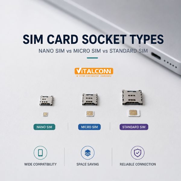
Micro-SIM (3FF)
15 × 12
6 contacts
Older smartphones, IoT gateways
Nano-SIM (4FF)
12.3 × 8.8
6 contacts
Current standard
Common SIM socket configurations:
Standard 6-pin (VCC, RST, CLK, GND, VPP, I/O): The baseline SIM interface used in 2G/3G/4G modules
8-pin (adds 2 reserved/detect pins): Offers dedicated card-detect functionality without consuming a separate PCB switch
Hinge-type / tray-type: Used in smartphones — the SIM sits in a metal tray that slides into the connector
Push-push: The card clicks in and clicks out via a spring mechanism — common in IoT modules and industrial devices
SD Card Sockets
SD (Secure Digital) card sockets support the most common removable storage format. The connector must handle data rates ranging from a few MB/s (standard SD) to nearly 4 GB/s (SD Express with PCIe Gen 4).
SD card form factors:
Form Factor
Dimensions (mm)
Contact Pins
Primary Uses
Standard SD
32 × 24 × 2.1
9 pins
Digital cameras, industrial PCs, medical devices
miniSD
21.5 × 20 × 1.4
11 pins
Legacy; largely phased out
microSD
15 × 11 × 1.0
8 pins
Smartphones, drones, IoT, automotive dashcams
SD bus interface standards supported through the connector:
Standard
Max Speed
Bus Type
Default Speed
12.5 MB/s
SD Bus
High Speed
25 MB/s
SD Bus
UHS-I
104 MB/s
SD Bus (single row)
UHS-II
312 MB/s
SD Bus (dual row)
UHS-III
624 MB/s
SD Bus (dual row)
SD Express (Gen 3)
985 MB/s
PCIe 3.0 ×1
SD Express (Gen 4)
1,969 MB/s
PCIe 4.0 ×1
⚠ Important: UHS-II and above require a second row of contacts on the card — the connector must support these additional pins. If your product targets high-speed data logging (4K/8K video, high-frame-rate photography), verify that the socket supports the required bus interface.
TF (TransFlash) Card Sockets
TF card, or TransFlash, is simply the original name for what became the microSD standard. In practice today, "TF card" and "microSD card" refer to the same physical card format (15 × 11 × 1.0 mm).
However, in the Chinese and broader Asian electronics supply chain, the term "TF card socket" is widely used as a distinct product category name. Some low-cost TF-only sockets may lack full microSD protocol support (e.g., no SDHC/SDXC compatibility), so it's important to confirm the specification.
In summary: A TF card socket = a microSD card socket. But when sourcing, always verify the supported capacity standard (SDHC, SDXC, SDUC) and bus speed class.
Smart Card Sockets
Smart Card sockets interface with chip-embedded cards using the ISO 7816 standard. These are the connectors inside POS terminals, EMV payment readers, access control panels, government ID readers, and set-top boxes for conditional access.
Key characteristics:
8 contacts per ISO 7816: VCC, RST, CLK, GND, VPP, I/O, and two reserved (RFU)
Contact layout: A defined pattern of gold-plated pads on the card surface — spring pins align precisely with these pads
Card detection: Often includes a dedicated presence-detection switch separate from signal contacts
Durability: EMV payment terminals require connectors rated for hundreds of thousands of insertions
Types by mounting:
Type
Description
Typical Use
Landing contact
Card inserted into slot; spring contacts press down onto surface pads
POS terminals, ID readers, set-top boxes
Sliding contact
Card slides along guide rails; contacts engage during insertion
ATM card readers, access control panels
Hinge / cover type
Card placed in tray; hinged cover presses down to lock
Industrial controllers, medical devices
Card Edge Connectors
Card edge connectors are a different beast. Unlike the sockets above — which accept removable memory/identity cards — a card edge connector mates directly with the gold-plated edge fingers of a PCB daughter card (plug-in card).
Common applications:
PCIe add-in cards (graphics cards, network adapters, NVMe SSDs)
Industrial backplane systems (VME, CompactPCI)
Embedded computer modules (COM Express, SMARC)
Custom plug-in modules in instrumentation and test equipment
Key parameters:
Parameter
Typical Range
Pitch
0.5 mm – 2.54 mm
Contact count
20 – 500+ positions
Plating
Gold over nickel, 0.76 μm (30 μin) minimum
Current per contact
1–3 A (standard); up to 10 A (power contacts)
Mounting
Through-hole (most common), surface-mount
Card edge connectors eliminate the cost and reliability concerns of a separate connector pair — the PCB card is the connector. This makes them cost-effective for high-volume designs but demands tight PCB fabrication tolerances at the card edge.
Insertion & Ejection Mechanisms
The way a card goes in and comes out is a crucial mechanical design choice:
Mechanism
How It Works
Best For
Pros
Cons
Push-Push
Push to lock; push again to eject (spring)
IoT, industrial, cameras
Tactile feedback; secure lock
Higher cost; taller profile
Push-Pull
Push in; pull out (friction fit)
Cost-sensitive, low-frequency
Simplest; lowest cost
No positive lock
Hinge / Cover
Lift cover, insert card, close to lock
High-vibration, medical
Excellent retention; dust protection
Needs clearance above; slower
Tray (Drawer)
Card sits in metal tray; tray slides in
Smartphones, tablets
Sleek; supports IP sealing
Most expensive; custom enclosure
Card Edge (PCB slot)
Daughter card slides directly into connector
Backplanes, PCIe
Eliminates connector pair
No removable media support
Design note: The push-push mechanism is the most popular choice for devices where the card is infrequently accessed (IoT, industrial). The tactile "click" confirms proper seating, and the spring eject prevents the user from pulling the card out at an angle — a common cause of bent pins.
Pin Configuration Quick Reference
SIM Card Socket — 6-Pin Standard
Pin
Name
Function
C1
VCC
Power supply (1.8V, 3V, or 5V)
C2
RST
Reset signal
C3
CLK
Clock input
C4
GND
Ground
C5
VPP
Programming voltage (rarely used)
C6
I/O
Serial data input/output (half-duplex)
Additional pins (8-pin variant): C7 and C8 are typically reserved for future use or assigned as card-detect switches.
SD / microSD Card Socket — 9-pin (SD) / 8-pin (microSD)
Pin (SD)
Pin (microSD)
Name
Function
1
1
DAT3 / CS
Data line 3 / Card Select (SPI)
2
2
CMD / DI
Command / Data In (SPI)
3
3
VSS1
Ground
4
4
VDD
Supply voltage (2.7–3.6V)
5
5
CLK
Clock
6
6
VSS2
Ground
7
7
DAT0 / DO
Data line 0 / Data Out (SPI)
8
8
DAT1 / IRQ
Data line 1 / Interrupt
9
—
DAT2
Data line 2
For UHS-II microSD cards, a second row of 8 contacts is present on the card, and the connector must include matching bottom-row pins.
Card Detection & Write Protection
Most SD sockets include two additional mechanical switches:
Card Detect (CD): A normally-open switch that closes when a card is fully inserted. The host uses this to trigger card initialization.
Write Protect (WP): A switch that detects the position of the SD card's mechanical write-protect slider. When in the "lock" position, the host firmware writes to read-only mode.
How to Select a Card Socket Connector: 7 Critical Parameters
1. Card Format Compatibility
The non-negotiable starting point. Your connector must match the exact card form factor: Nano-SIM (4FF), microSD, standard SD, full-size Smart Card, etc. A connector designed for Micro-SIM will not accept a Nano-SIM without an adapter — and adapters introduce additional contact resistance and reliability risks.
Common combo/hybrid socket options:
SIM + microSD combo (shared tray, common in smartphones)
Dual SIM sockets (two SIMs in one connector)
SD + microSD adapter sockets
2. Insertion Mechanism
Use Case
Recommended Mechanism
Card inserted once during manufacturing
Push-pull (simplest, lowest cost)
Card accessed for occasional maintenance (IoT)
Push-push (positive lock, tactile feedback)
High vibration, vehicle-mounted
Hinge/lock type
Consumer smartphone/tablet
Tray type
Frequent card swaps (photography, field data)
Push-push or tray, high cycle rating
3. Durability — Insertion Cycle Rating
This is the number of guaranteed insertion/extraction cycles before contact resistance exceeds the specification limit:
Consumer-grade push-push SD socket: 5,000–10,000 cycles
Industrial/automotive push-push SIM socket: 10,000–30,000 cycles
Smart Card landing-contact (POS terminal): 100,000–500,000 cycles
Card edge connector (PCIe): 50–100 cycles
💡 Tip: The cycle rating in the datasheet is under laboratory conditions. In the field, real-world cycles are harder. Derate the published cycle rating by 30–50% for reliability margin.
4. ESD Protection
Card sockets are an ESD entry point — a charged human body touches the card, which transfers charge through the socket contacts to sensitive ICs. Look for sockets with grounded metal shells that discharge ESD to the PCB ground plane before it reaches the signal pins. Minimum target: survive 8 kV contact discharge (IEC 61000-4-2 Level 4).
5. Mounting Type
Mounting
Pros
Cons
Best For
SMT (surface-mount)
Reflow-compatible; lower profile
Lower mechanical strength
Consumer electronics
Through-hole
Excellent strength; visible joints
More PCB area
Industrial, automotive
SMT with locating pegs
SMT convenience + alignment
Slightly higher cost
Most modern designs
6. Contact Plating
Gold flash (0.1–0.2 μm): Minimum acceptable. Adequate for low-cycle consumer devices.
Gold plate (0.76 μm / 30 μin): Industry standard for reliable connectors. Good wear resistance and corrosion protection.
Heavy gold (1.27 μm / 50 μin+): For high-cycle, high-reliability applications (POS terminals, medical).
7. Environmental Rating
Condition
What to Require
-40°C to +85°C operation
Industrial-temperature-rated LCP housing
+85°C to +125°C (automotive)
Automotive-grade LCP, AEC-Q200 validated
High humidity / condensing
Gold plating ≥ 0.76 μm, sealed actuator
Salt spray / corrosive
Stainless steel shell; enhanced nickel underplate
IP-rated enclosure required
Tray-type with gasket seal
Quick Decision Matrix
Your Requirement
Recommended Configuration
IoT cellular module (factory-only SIM insertion)
6-pin push-pull Nano-SIM, SMT, 500+ cycles
IoT with field-serviceable SIM
6-pin push-push Nano-SIM, SMT with pegs, 5,000+ cycles
Automotive telematics
6-pin push-push Micro-SIM, through-hole, 125°C rated, 10,000+ cycles
Digital camera (frequent SD swaps)
9-pin push-push SD, through-hole, 10,000+ cycles
POS payment terminal
8-contact ISO 7816 landing-type Smart Card socket, 200,000+ cycles
Dual SIM + microSD smartphone
Combo tray-type socket (2× Nano-SIM + microSD), SMT
PCIe add-in card
Card edge connector, 1.0 mm pitch, through-hole, 30 μin gold
Embedded system backplane
Card edge connector, 2.54 mm pitch, through-hole, selective gold
Common Applications
Industry
Application
Typical Card Socket Type
Telecom / IoT
Cellular modules, gateways, trackers
Nano-SIM (4FF) push-push or push-pull
Consumer Electronics
Smartphones, tablets, cameras, drones
SIM tray + microSD push-push
Automotive
Telematics, dashcams, infotainment
Micro-SIM push-push (auto-grade), microSD
Payment / Security
POS terminals, ATM, access control
ISO 7816 Smart Card, EMV Level 1 certified
Industrial
PLCs, HMIs, data loggers
Standard SD push-push, through-hole
Medical
Patient monitors, imaging, diagnostic
Standard SD or Smart Card, hinge/lock type
Computing
Servers, workstations, embedded modules
Card edge (PCIe, COM Express)
About VITALCONN
VITALCONN Electronics Technology is a professional manufacturer of card socket connectors and precision interconnect solutions based in Shenzhen, China. With over 15 years of experience, we serve OEMs, EMS providers, IoT module manufacturers, and connector distributors worldwide.
Our card socket connector product range includes:
SIM Card Sockets — Nano-SIM (4FF), Micro-SIM (3FF), Mini-SIM (2FF); 6-pin and 8-pin configurations; push-push, push-pull, and hinge types
SD Card Sockets — Standard SD (9-pin), microSD (8-pin); push-push and push-pull; with and without card-detect/write-protect switches
TF (microSD) Sockets — Full microSD/SDHC/SDXC compatible; SMT and through-hole
Smart Card Sockets — ISO 7816 compliant; 8-contact landing and sliding types
Combo Sockets — SIM + microSD dual-purpose trays; dual SIM configurations
Card Edge Connectors — Custom pitch, pin count, and plating specifications
Quality certifications: ISO 9001, ISO 14001, RoHS, REACH, UL
MOQ: 100 pieces for standard catalog items
Need a sample, 3D model, or a custom card socket configuration?
📧 sales@vitalconn.com | 🌐 www.vitalconngroup.com
FAQ
Q1: What is the difference between push-push and push-pull card sockets?
Push-push uses an internal spring-and-cam mechanism. You push the card in to lock it; push again to eject it. It provides a tactile "click" confirmation and prevents the card from accidentally being pulled out. Push-pull is a simple friction fit — you push the card in and pull it out with your fingers. It's cheaper and lower profile but does not lock the card. Push-push is preferred for most professional designs because the positive-lock mechanism prevents contact bounce and accidental disconnection.
Q2: How do I know if I need a 6-pin or 8-pin SIM socket?
6-pin is the standard SIM interface (VCC, RST, CLK, GND, VPP, I/O) and is sufficient for almost all 2G/3G/4G cellular modules. 8-pin adds two extra contacts, typically used for a dedicated card-detect function or reserved for future use. Unless your cellular module datasheet specifically requires an 8-pin interface or a separate card-detect signal, a 6-pin socket is adequate. Check your module's hardware design guide.
Q3: Can a microSD socket accept a TF card?
Yes. A TF (TransFlash) card is mechanically identical to a microSD card (15 × 11 × 1.0 mm). A standard microSD socket will accept both. However, some very old TF-only sockets from the early 2000s may not support SDHC/SDXC capacity standards. When sourcing, confirm that the socket datasheet lists SDHC and SDXC compatibility.
Q4: How many insertion cycles should I specify?
It depends entirely on the use case, and over-specifying costs money unnecessarily:
Factory-once, never touched again (IoT sensor): 500 cycles is more than enough
Occasional field service (industrial gateway): 5,000 cycles
Frequent card swaps (camera, field data logger): 10,000+ cycles
Continuous use (POS terminal, ATM): 200,000+ cycles
Derate the published cycle rating by 30–50% for reliability margin — real-world insertions are harder on connectors than lab tests.
Q5: Do I need a card-detect switch on my SD socket?
If your product uses a removable SD card and needs to respond to card insertion/removal (initialize the filesystem, unmount before removal, trigger a firmware action), then yes — the card-detect switch is essential. Without it, the host has no way to know that a card has been inserted or removed without polling the card bus, which wastes power and increases firmware complexity. For designs where the card is factory-installed and never removed, the CD switch can be omitted to save cost.
Read More




 IPv6 network supported