Leave A Message
If you are interested in our products and want to know more details,please leave a message here,we will reply you as soon as we can.

Products
Networking Connectors LAN Transformer ModulesGigabit LAN Transformer 10/100/1000M SMT 350uH 1500V PoE 720mA TG24010S1H2
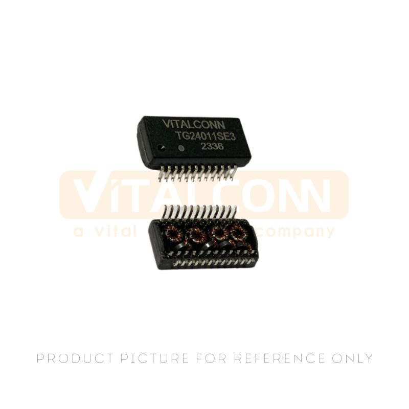
The TG24010S1H2 is a 10/100/1000 Mbps Gigabit LAN transformer module designed for high-speed Ethernet applications. As an advanced 10/100/1000M Gigabit LAN Transformer SMT, it provides superior signal integrity, electrical isolation, and common-mode noise suppression for Gigabit Ethernet interfaces operating up to 1000BASE-T.
The open-header surface-mount design simplifies PCB layout and supports automated assembly, while PoE-ready current handling up to 720mA enables reliable operation in Power over Ethernet designs.
Part Number :
TG24010S1H2Product Category :
LAN Magnetics
Product Overview
This TG24010S1H2 is a single-port Gigabit Ethernet LAN transformer module featuring a 10/100/1000M Gigabit LAN Transformer SMT design with open header construction for simplified PCB integration. Fully compliant with IEEE 802.3 and ANSI X3.263 standards, the module delivers 350 µH minimum open-circuit inductance, 1:1 turns ratio, and 1500 VAC isolation voltage across the full -40°C to +85°C operating temperature range.
With PoE current-handling capability up to 720mA (IEEE 802.3at Type 2), the TG24010S1H2 is engineered for next-generation network equipment requiring both high-speed data and power delivery over standard Ethernet cabling.
Product Specifications / Attributes
10/100/1000 Base-T (IEEE 802.3, ANSI X3.263)
|
Application Standard |
10/100/1000 Base-T (IEEE 802.3, ANSI X3.263) |
|
Package Type |
Surface Mount (SMT), Open Header |
|
Turns Ratio |
1:1 (±3%) |
|
OCL (Open Circuit Inductance) |
350 µH Min @ 100kHz, 0.1Vrms, 8mA DC Bias |
|
Leakage Inductance (Primary) |
0.5 µH Max @ 10kHz, 0.1Vrms |
|
DCR (DC Resistance) |
0.9 Ω Max (Primary) / 1.2 Ω Max (Secondary) |
|
Cww (Interwinding Capacitance) |
35 pF Typ (Primary to Secondary) |
|
Insertion Loss |
-1.1 dB Max (1 ~ 100 MHz) |
|
Return Loss |
-18 dB Min (1~40 MHz), -16 dB Min (40~60 MHz), -12 dB Min (60~100 MHz) |
|
CMRR (Common Mode Rejection) |
-40 dB Min (1~60 MHz), -35 dB Min (60~100 MHz) |
|
Crosstalk |
-30 dB Min (1~100 MHz) |
|
Isolation Voltage (HIPOT) |
1500 VAC RMS (3 seconds) |
|
PoE Current Capability |
720 mA (IEEE 802.3at Type 2 Compatible) |
|
Operating Temperature Range |
-40°C to +85°C |
|
Storage Temperature Range |
-55°C to +125°C |
|
Reflow Soldering Peak Temperature |
≤ 250°C (10 seconds) |
|
Reflow Cycles |
3 Times Maximum Recommended |
|
RoHS Compliance |
Yes, Lead-Free |
|
Packaging |
Tape & Reel — 400 pcs/reel, 2400 pcs/box |
Features&Benefits
Gigabit Ethernet 1000BASE-T Compliant providing key advantages.
Packing Details
If you need detailed information about our packaging specifications and requirements, please feel free to contact us directly. We will be happy to provide you with the details.
Applications
Frequently Asked Questions (FAQ)
Q: What PoE standards does the TG24010S1H2 Gigabit LAN Transformer support?
A: The TG24010S1H2 supports IEEE 802.3at (PoE+) with a continuous current rating of 720mA, enabling power delivery up to 25.5W per port. It is backward compatible with IEEE 802.3af (PoE) applications at lower current levels and is compatible with Type 2 PD designs. For IEEE 802.3bt (PoE++) high-power applications requiring 60W or more, please consult VITALCONN for alternative transformer recommendations.
Q: Can this 10/100/1000M Gigabit LAN Transformer SMT module be wave soldered?
A: The TG24010S1H2 is designed specifically for reflow soldering with a peak temperature of ≤250°C for 10 seconds and a maximum of 3 reflow cycles. Wave soldering is not recommended as the open-header SMT package may not reliably withstand the solder wave process. Please follow the recommended reflow profile provided in the product datasheet.
Q: What is the recommended PCB land pattern and clearance for the 1500V isolation rating?
A: The PCB land pattern and recommended creepage/clearance distances to maintain the 1500 VAC isolation rating are detailed in the TG24010S1H2 product drawing. As a general guideline, a minimum creepage distance of 4.0mm between primary and secondary side traces is recommended for reinforced isolation at this voltage level. Always design PCB layout to comply with applicable safety standards (IEC 60950-1, IEC 62368-1) for your target market.
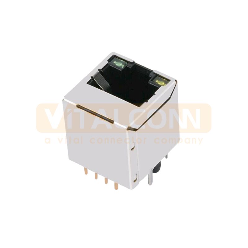
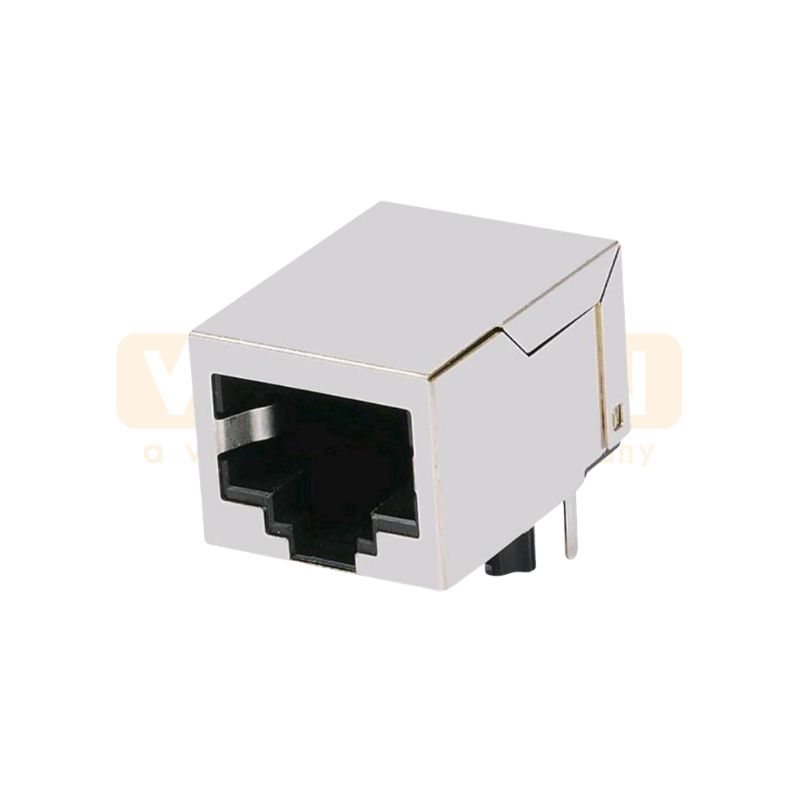
This is a vertical-mounted RJ45 1x1 modular jack connector equipped with status indicator LEDs (green and yellow). It is designed for network communication applications.
Read More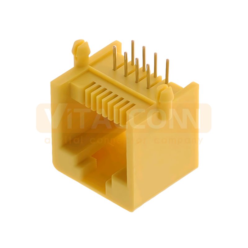
The JU112A01UPB7 is a high-performance, single-port (1x1) RJ45 modular jack designed for space-constrained PCB applications. Featuring a "Tab Up" orientation and integrated LED indicators, this connector provides robust EMI shielding and reliable data transmission, making it an ideal choice for networking and industrial communication equipment.
Read More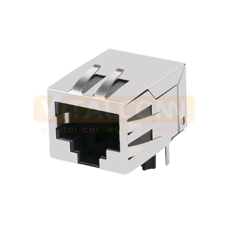
This is a single-port (1x1) RJ45 modular jack connector featuring a low-profile design and 10 flat pins. It is a shielded connector intended for through-hole mounting onto printed circuit boards (PCBs) .
Read More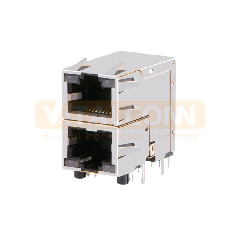
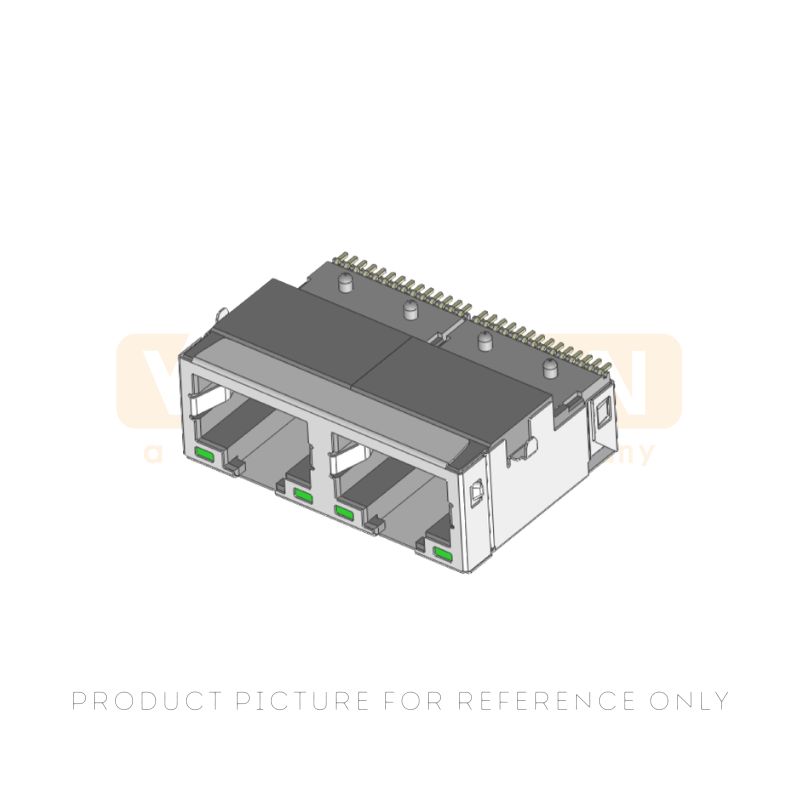
This is a dual-port (2x1) RJ45 modular jack connector. It is a shielded connector designed for through-hole mounting onto PCBs and features integrated status indicator LEDs for each port.
Read More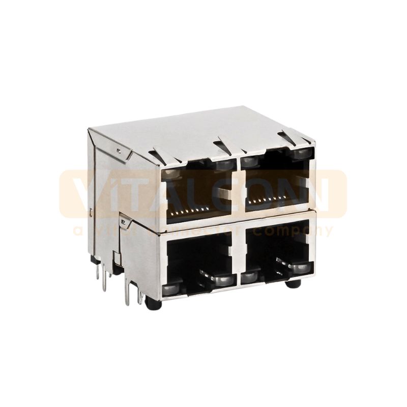
This is a dual-port (2x2) RJ45 modular jack connector. It is a shielded connector designed for through-hole mounting onto PCBs and features integrated status indicator LEDs for each port.
Read More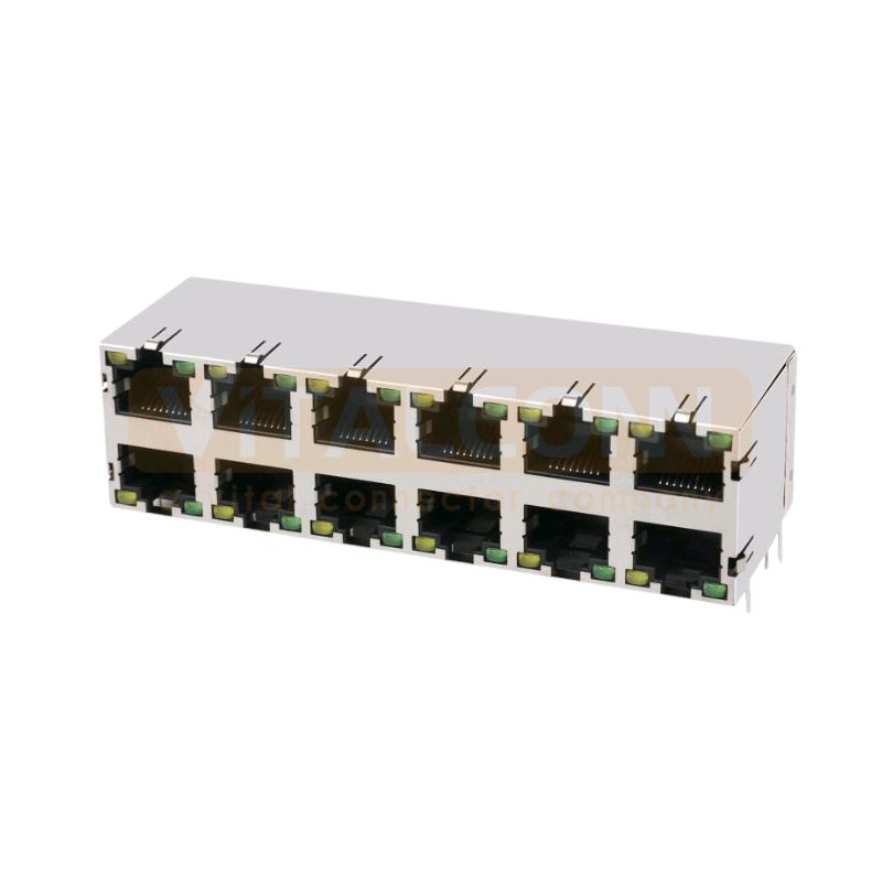
This is a twelve-port (2x6) shielded RJ45 modular jack connector with integrated status indicator LEDs.
Read More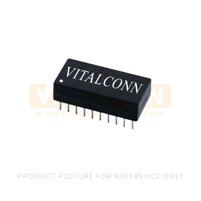
This is a dual-port, 10/100 Base-T LAN transformer module designed for through-hole (DIP) mounting on printed circuit boards (PCBs). It integrates magnetics to provide signal isolation, impedance matching, and common-mode noise rejection for Ethernet interfaces.
Read More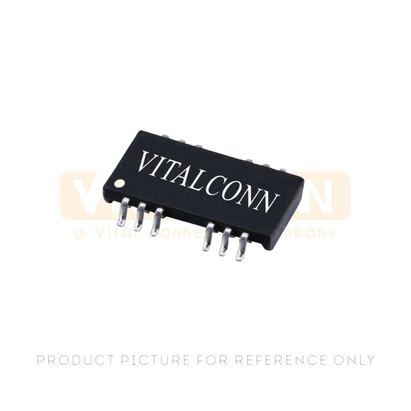
This is a high-performance LAN Transformer Module designed for 10/100BASE-TX Ethernet applications. It features a dual-port configuration and a 20-pin DIP package, providing essential signal isolation and noise filtering for reliable network communication.
Read More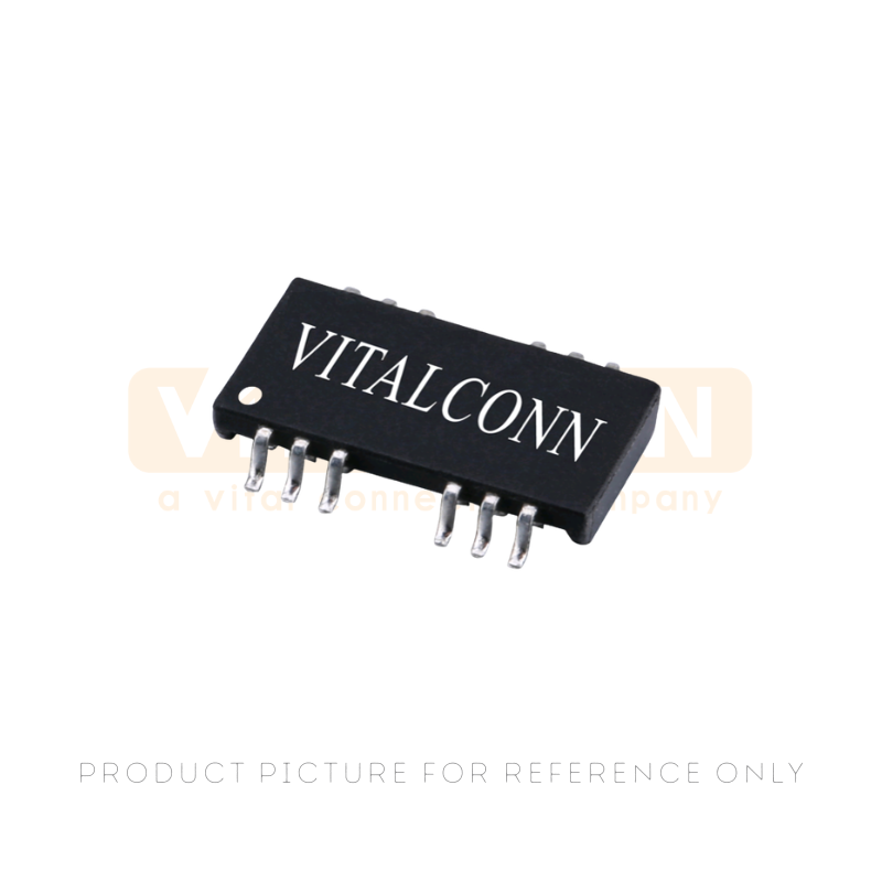
This is a 10/100 BASE-T SMT LAN Transformer Module designed for reliable signal isolation and impedance matching in Ethernet applications.
Read More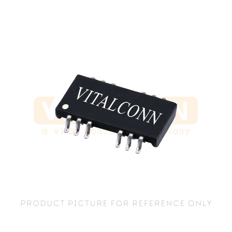
This is a 10/100 BASE-T SMT LAN Transformer Modules designed for signal isolation and impedance matching in Ethernet applications, ensuring reliable data transmission.
Read More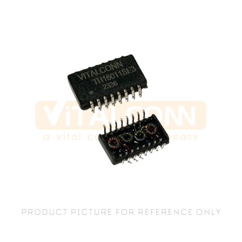
This is a 10/100 BASE-T SMT LAN Transformer Modules designed for signal isolation and common-mode noise rejection in Ethernet applications, ensuring reliable data transmission.
Read More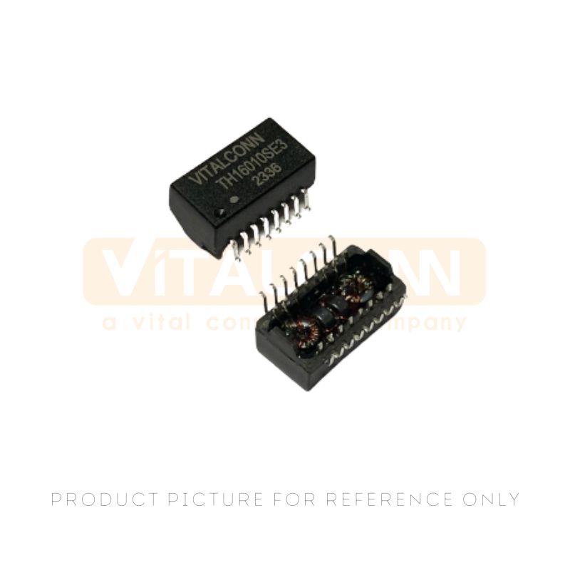
This is a 10/100 BASE-T SMT LAN Transformer Modules designed for signal isolation and impedance matching in Ethernet applications, ensuring reliable data transmission.
Read More
 IPv6 network supported
leave a message
Scan to Wechat :

Scan to WhatsApp :