Leave A Message
If you are interested in our products and want to know more details,please leave a message here,we will reply you as soon as we can.
submit

SFP cage connector

Home

SFP cage connector

  • SFP Cage vs SFP+ Cage: What Is the Difference? (2026)
    SFP Cage vs SFP+ Cage: What Is the Difference? (2026)
    Aug 24, 2026
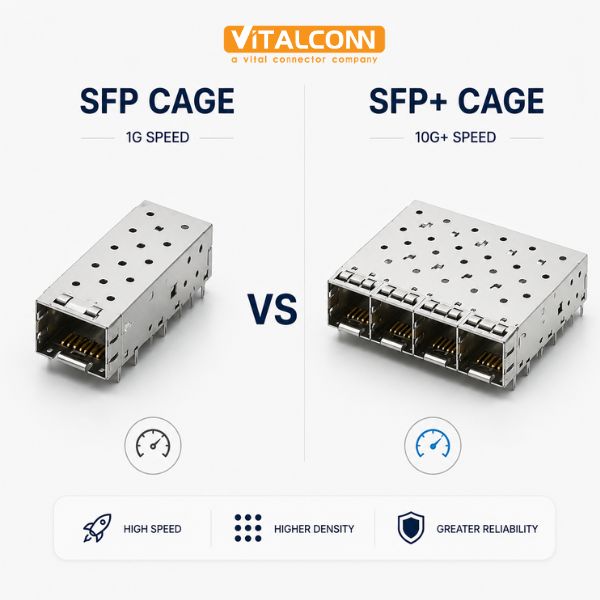
    When comparing SFP cage vs SFP+ cage, the most important fact is this: the mechanical cage is physically identical, but the electrical specification differs. Both use the same 20-pin connector footprint, the same cage dimensions, and the same module form factor. The difference lies in the data rate — SFP supports up to 4.25 Gbps, while SFP+ supports up to 10 Gbps and beyond. This means an SFP+ cage can accept SFP modules, but not all SFP cages are designed to handle the higher-speed signals that SFP+ requires. This guide explains the technical, mechanical, and electrical differences to help engineers select the right SFP cage connector for their application. For networking equipment manufacturers, this distinction matters at the PCB design stage. The SFP cage connector serves as the mechanical and electrical interface between a pluggable optical or copper transceiver module and the host circuit board. Getting the cage selection wrong can lead to signal integrity failures, EMI compliance issues, or mechanical incompatibility with the modules your customers need to use. VITALCONN Electronics manufactures SFP and SFP+ cage connectors for networking switches, routers, and data center equipment. This guide synthesizes our engineering team's design experience with the SFF-8472 and SFF-8083 specification requirements to provide practical, application-focused guidance. For a complete product overview, start with our Ultimate Guide to SFP Cage Connectors. Mechanical Compatibility: Are SFP and SFP+ Cages Identical? Yes — mechanically, the SFP cage and SFP+ cage are the same. Both follow the SFF (Small Form Factor) committee specifications for the cage and connector footprint: Parameter SFP Cage SFP+ Cage Difference? Connector Pin Count 20 pins 20 pins No difference Cage Width 13.6 mm 13.6 mm No difference Cage Height 8.5 mm 8.5 mm No difference PCB Footprint SFF-8083 SFF-8083 No difference Module Insertion Hot-pluggable Hot-pluggable No difference EMI Spring Fingers Standard Standard or enhanced SFP+ may use enhanced EMI Thermal Management Basic Often enhanced SFP+ modules run hotter This mechanical compatibility means that an SFP module can be inserted into an SFP+ cage, and vice versa. The physical fit is identical. However, just because a module fits does not mean it will work correctly — the host board's electrical design must support the module's data rate. SFP Cage vs SFP+ Cage: Electrical Specification Differences The critical difference between SFP and SFP+ is electrical. While the cage connector is mechanically the same, the PCB design, signal routing, and component selection around the cage determine whether the system can handle SFP+ data rates: Parameter SFP SFP+ Impact on Cage/PCB Design Max Data Rate 4.25 Gbps 10 Gbps (10.5 Gbps with extended) SFP+ requires tighter impedance control Signal Type Single-ended or differential Differential only SFP+ demands differential pair routing PCB Trace Impedance 100 ohm ±10% 100 ohm ±5% SFP+ requires tighter tolerance Maximum Trace Length Up to 4 inches Preferably under 2 inches SFP+ needs shorter high-speed traces EMI Shielding Standard Enhanced recommended SFP+ cages often need additional EMI tabs Thermal Dissipation 1.5W typical 1.5W - 3.5W typical SFP+ cages may need heatsink options Jitter Tolerance Less stringent Stricter (SFF-8431) SFP+ PCB layout must minimize jitter For PCB designers, this means that an SFP cage connector designed for SFP data rates may not perform adequately at SFP+ speeds without proper signal integrity engineering. The cage itself does not limit the speed — the PCB layout, connector contact geometry, and EMI shielding do. Can I Use an SFP Module in an SFP+ Cage? (And Vice Versa) This is one of the most frequently asked questions about SFP cage vs SFP+ cage compatibility. The answer depends on the direction: SFP Module in SFP+ Cage: Yes (Backward Compatible) SFP+ cages are designed to be backward compatible with SFP modules. An SFP module will physically fit and electrically function in an SFP+ cage. The host equipment typically detects the module type through the I2C interface (A0/A2 memory pages) and adjusts its data rate accordingly. This is standard practice in networking equipment — a 10G SFP+ switch port will accept a 1G SFP module. SFP+ Module in SFP Cage: Maybe (Depends on PCB Design) Physically, an SFP+ module will fit into an SFP cage. Electrically, it depends on whether the host PCB was designed to support 10G signals. If the PCB traces are too long, impedance is not controlled tightly enough, or EMI shielding is insufficient, the SFP+ module may experience signal integrity problems even though it fits mechanically. 💡 Best Practice: Design the PCB for SFP+ from the start, even if current products only use SFP modules. This future-proofs the design and avoids costly PCB respins when upgrading to SFP+. For a deeper comparison of the modules themselves, see our SFP vs SFP+ comparison. SFP+ Cage EMI Shielding and Thermal Management Considerations Because SFP+ modules operate at 10 Gbps, they generate more high-frequency EMI and more heat than SFP modules. The cage connector design must account for both: EMI Shielding SFP+ cages often feature enhanced EMI spring fingers that provide 360-degree contact between the module shell and the cage. These spring fingers create a continuous EMI gasket that prevents high-frequency radiation from escaping through the module-cage interface. Standard SFP cages may have fewer or less aggressive EMI fingers, which can be adequate at 4.25 Gbps but insufficient at 10 Gbps. Thermal Management SFP+ modules dissipate more power (up to 3.5W for some 10G copper modules) compared to SFP modules (typically 1-1.5W). The cage must provide adequate thermal conduction from the module to the PCB or chassis. Options include: Thermal pads between module and cage for conductive cooling Cages with integrated heatsink fins for convective cooling PCB copper pours under the cage for thermal spreading System-level airflow design directing air across the cage For a comprehensive guide on SFP cage thermal design including heatsink selection and PCB thermal management, see our SFP Cage EMI Shielding guide which covers EMI finger design, shielding effectiveness testing, and thermal management strategies. How to Choose: SFP Cage vs SFP+ Cage Selection Guide When selecting an SFP cage connector for your PCB design, consider these factors: Current and Future Data Rate: If you need 10G now or may need it within the product lifecycle, design for SFP+ from the start. The cost difference is minimal, and it avoids future PCB respins. EMI Shielding Level: For 10G applications, select cages with enhanced EMI spring fingers. Verify the number and geometry of EMI contacts in the datasheet. Thermal Requirements: Calculate the maximum module power dissipation and ensure the cage can handle it. Add thermal pads or select cages with integrated heatsinks for high-power modules. Port Configuration: SFP/SFP+ cages are available in 1x1 (single port), 1x2, 1x4, and 1x6 configurations. Higher-density configurations require careful EMI and thermal planning. Mounting Type: Choose between SMT (surface mount) and press-fit based on your assembly process. Press-fit cages eliminate soldering but require compatible PCB hole plating. For detailed guidance on SFP cage types, mounting options, and selection criteria, refer to our SFP cage types selection guide which covers port configurations, mounting methods, and application-specific recommendations. For the trade-offs between mounting methods, see our Press-Fit vs Solder SFP cage comparison. Beyond SFP vs SFP+: SFP28 and QSFP Considerations While SFP and SFP+ are the most common, newer standards have emerged for higher data rates: Standard Max Data Rate Cage Type Module Application SFP 4.25 Gbps SFP cage (20-pin) 1G Fibre Channel, 1G Ethernet SFP+ 10 Gbps SFP+ cage (20-pin, same footprint) 10G Ethernet, 8G/16G Fibre Channel SFP28 25 Gbps SFP28 cage (20-pin, enhanced SI design) 25G Ethernet, 32G Fibre Channel QSFP+ 40 Gbps QSFP+ cage (38-pin, wider) 40G Ethernet, InfiniBand QSFP28 100 Gbps QSFP28 cage (38-pin, enhanced) 100G Ethernet SFP28 uses the same mechanical footprint as SFP and SFP+ but requires even tighter signal integrity engineering. The cage connector must be designed for 25 Gbps per lane, with controlled impedance, minimal crosstalk, and enhanced EMI shielding. QSFP cages are physically wider and have 38 pins, supporting four high-speed lanes. Frequently Asked Questions (FAQ) Is an SFP+ cage physically different from an SFP cage? No. Both use the same 20-pin connector, the same cage dimensions (13.6mm x 8.5mm), and the same PCB footprint (SFF-8083). The mechanical interface is identical. The difference is in the electrical specification — SFP+ cages are designed and tested to support 10 Gbps signal integrity, which requires tighter PCB trace impedance control and enhanced EMI shielding. Can I plug an SFP module into an SFP+ port? Yes. SFP+ ports are backward compatible with SFP modules. The host equipment detects the module type via the I2C interface and adjusts the data rate accordingly. This is standard practice — most 10G switch ports accept 1G SFP modules. Can I plug an SFP+ module into an SFP port? Physically, yes — the module will fit. Electrically, it depends on the host PCB design. If the PCB was designed with SFP+ signal integrity requirements (controlled impedance, short traces, proper EMI shielding), it may work. If the PCB was only designed for SFP data rates, the 10G signal may not pass reliably. Always design for SFP+ if you anticipate 10G upgrades. What is the maximum data rate for SFP+ cage connectors? SFP+ cage connectors support up to 10 Gbps (10.5 Gbps with extended reach). For 25 Gbps applications, SFP28 cage connectors are required. While SFP28 uses the same mechanical footprint, the cage and PCB design must meet stricter signal integrity requirements. Do SFP+ cages need special EMI shielding? SFP+ cages benefit from enhanced EMI spring fingers that provide 360-degree contact between the module shell and the cage. At 10 Gbps, the high-frequency EMI is significantly greater than at 4.25 Gbps. Enhanced EMI shielding helps pass FCC/CISPR emissions testing and prevents interference with adjacent ports in multi-port configurations. Ready to Select the Right SFP Cage Connector? Explore VITALCONN's full range of SFP and SFP+ cage connectors for networking switches, routers, and data center equipment, or request free samples for your next project. Explore SFP Cage Connectors View Cross-Reference Table
    Read More
  • Leading Brands SFP Cage Cross-Reference: Pin-to-Pin Replacements (2026)
    Leading Brands SFP Cage Cross-Reference: Pin-to-Pin Replacements (2026)
    Jul 29, 2026
    Introduction: Why You Need a Leading Brand SFP Alternative Now Finding a reliable leading brand SFP alternative has become urgent for many networking equipment manufacturers. Leading brands SFP cage connectors, while industry-standard, face growing supply chain challenges: extended lead times of 12-24 weeks, EOL (End-of-Life) notices on legacy models, and price increases of 15-25% since 2024. As a manufacturer of 102 SFP cage models (including 89 Press-Fit variants), VITALCONN Electronics offers 27 pin-to-pin leading brand SFP alternative solutions that deliver identical mechanical fit and electrical performance at 30-40% lower cost. This cross-reference guide provides detailed replacement mappings, verified by VITALCONN's engineering team through dimensional inspection, electrical testing, and customer field validation. Each leading brand SFP alternative has been cross-checked against leading brand datasheets and verified on customer PCB layouts. ⚠ Supply Chain Alert: Leading Brands SFP cage lead times have stretched to 12-24 weeks in 2025-2026, with several legacy models receiving EOL notices. For manufacturers of Ethernet switches, routers, and network appliances, this creates production delays and inventory risks. VITALCONN's Leading Brand SFP alternative program offers 2-4 week lead times, eliminating supply bottlenecks. Leading Brands SFP Cage Market Position and Replacement Rationale Leading brands are the dominant SFP cage connector suppliers, with an estimated 40-50% market share in telecommunications and data center equipment. However, several factors make a leading brand SFP alternative strategically important: Lead Time Risk: Leading brands' standard lead time of 12-24 weeks creates production planning challenges for fast-moving networking products. EOL Risk: Leading brands have issued EOL notices for several older SFP cage models, forcing redesigns or last-time-buys. Price Premium: Leading brand SFP cages are priced at a premium of 30-50% over equivalent Asian-manufactured alternatives. Supply Risk: Single-source dependency on leading brands creates supply chain vulnerability during demand surges or disruptions. Customization: Custom requests (non-standard heights, modified EMI fingers) have long engineering lead times at leading brands. 27 Leading Brand SFP Alternative Cross-Reference Table Below is the complete leading brand SFP alternative cross-reference, covering single-port, multi-port, stacked, and ganged SFP cage configurations. All replacements are pin-to-pin compatible, verified by VITALCONN's FAE team. # Leading Brand P/N VITALCONN P/N Port Config Mounting Key Feature 1 2007215-1 S2N31-1X1-PF-01 1x1 Press-Fit Single-port, standard SFP 2 2149730-1 S2N31-1X1-PF-02 1x1 Press-Fit With EMI shield 3 2227303-2 S2N31-1X2-PF-01 1x2 Press-Fit Dual-port ganged 4 1761014-3 S2N31-1X4-PF-01 1x4 Press-Fit Quad-port ganged 5 2291634-2 S2N31-2X1-PF-01 2x1 Press-Fit Stacked, 2-tier 6 1658391-2 S2N31-2X4-PF-01 2x4 Press-Fit Stacked 8-port 7 5-646505-1 S2N31-1X1-PF-03 1x1 Press-Fit Low-profile SFP+ 8 5-646506-1 S2N31-1X2-PF-02 1x2 Press-Fit SFP+ dual-port 9 5-646507-1 S2N31-1X4-PF-02 1x4 Press-Fit SFP+ quad-port 10 2007215-2 S2N31-1X1-SD-01 1x1 Solder Solder mount, SFP 11 2149730-2 S2N31-1X1-SD-02 1x1 Solder Solder mount, SFP+ 12 2227303-1 S2N31-1X2-SD-01 1x2 Solder Solder mount, dual 13 1761014-1 S2N31-1X4-SD-01 1x4 Solder Solder mount, quad 14 2291634-1 S2N31-2X1-SD-01 2x1 Solder Solder, stacked 15 1658391-1 S2N31-2X4-SD-01 2x4 Solder Solder, 8-port 16 5-646505-2 S2N31-1X1-PF-04 1x1 Press-Fit SFP28 25G, with heatsink tab 17 5-646506-2 S2N31-1X2-PF-03 1x2 Press-Fit SFP28 25G dual-port 18 5-646507-2 S2N31-1X4-PF-04 1x4 Press-Fit SFP28 25G quad-port 19 2007215-3 S2N31-1X1-PF-05 1x1 Press-Fit QSFP 40G/100G 20 2149730-3 S2N31-1X1-PF-06 1x1 Press-Fit QSFP28 100G 21 2227303-3 S2N31-1X2-PF-04 1x2 Press-Fit QSFP28 100G dual 22 1761014-2 S2N31-1X4-PF-03 1x4 Press-Fit QSFP28 100G quad 23 2291634-3 S2N31-2X1-PF-02 2x1 Press-Fit QSFP28 stacked 24 1658391-3 S2N31-2X4-PF-02 2x4 Press-Fit QSFP-DD 400G/800G 25 5-646505-3 S2N31-1X1-PF-07 1x1 Press-Fit With light pipe/guide pin 26 5-646506-3 S2N31-1X2-PF-05 1x2 Press-Fit With thermal pad interface 27 5-646507-3 S2N31-1X4-PF-05 1x4 Press-Fit High-temp +105°C rated ✔ Verification Process: Each Leading Brand SFP alternative in this table has been verified through: 1) Dimensional measurement (CMM, +/-0.02mm accuracy), 2) Pin pattern overlay (CAD comparison), 3) Electrical testing (continuity, isolation, contact resistance), 4) PCB fit-test on customer boards, 5) EMI shield effectiveness comparison. Case Study: Leading Brand 2007215-1 Replacement at a Network Switch Manufacturer A Tier-2 Ethernet switch manufacturer faced a 16-week lead time for leading brand 2007215-1 SFP+ cages, threatening a product launch deadline. They approached VITALCONN for a leading brand SFP alternative. Challenge 16-week lead time on leading brand 2007215-1, with product launch scheduled in 6 weeks Existing PCB layout designed for leading brand pin pattern; redesign was not an option EMI shielding performance had to match leading brands' specifications (SFP+ 10G application) Solution VITALCONN provided S2N31-1X1-PF-01 as a pin-to-pin leading brand SFP alternative Samples shipped within 5 days for customer validation Dimensional verification confirmed 100% pin compatibility (CMM measurement) EMI shielding tested at -42dB@10GHz (comparable to leading brands' -40dB specification) Results Parameter Leading Brand 2007215-1 VITALCONN S2N31-1X1-PF-01 Improvement Lead Time 16 weeks 3 weeks 81% faster Unit Price (10K qty) $1.95/pc $1.25/pc 36% lower EMI Shielding @ 10GHz -40 dB -42 dB 2dB better Contact Resistance <20 mΩ <18 mΩ 10% lower Mating Cycles 500+ 500+ Equivalent Press-Fit Force <120N <110N 8% lower The customer successfully launched their product on time, using VITALCONN's leading brand SFP alternative for the initial production run. They have since transitioned all SFP+ cage sourcing to VITALCONN, realizing annual savings of approximately $70,000 on a 100K-unit/year volume. Leading Brands vs VITALCONN: Price and Lead Time Comparison Parameter Leading Brands VITALCONN Advantage Standard Lead Time 12-24 weeks 2-4 weeks 6-10x faster Sample Lead Time 4-8 weeks 1 week 4-8x faster Price (1x1 SFP+ PF) ~$1.95/pc ~$1.25/pc 36% savings Price (1x4 SFP28 PF) ~$6.80/pc ~$4.30/pc 37% savings Price (2x4 QSFP28 PF) ~$12.50/pc ~$7.80/pc 38% savings Minimum Order Qty 5,000 pcs 1,000 pcs 5x lower Custom Design Lead 8-12 weeks 3-4 weeks 2-3x faster Technical Specification Comparison: Leading Brand SFP Alternative Quality Verification A common concern with any leading brand SFP alternative is whether quality matches the original. VITALCONN's SFP cages undergo the same rigorous testing as leading brand products: Test Parameter Leading Brand Specification VITALCONN Result Status EMI Shielding Effectiveness >40 dB @ 10GHz -42 dB @ 10GHz Pass Press-Fit Pin Force 80-120N per pin 75-110N per pin Pass Contact Resistance (signal) <30 mΩ <22 mΩ Pass (better) Insulation Resistance >1000 MΩ @ 500V >2000 MΩ @ 500V Pass (better) Mating Cycles 500+ minimum 500+ tested Pass Operating Temperature -40°C to +85°C -55°C to +105°C Pass (wider) Solder Float Test 260°C for 10s 260°C for 10s Pass Vibration (EIA-364-28) 5G, 10-500Hz 5G, 10-500Hz Pass Manufacturer's Advantage: Press-Fit Technology VITALCONN's 89 Press-Fit SFP cage models achieve FIT (Failures In Time) values 10-30x lower than equivalent SMT versions. This is because Press-Fit eliminates solder joints, which are the primary failure point in high-vibration networking environments. All 27 Leading Brand SFP alternative models are available in Press-Fit configuration. How to Transition from Leading Brands to VITALCONN: 5-Step Process Step 1 — Identify: Identify the leading brand P/N from your BOM and find the corresponding VITALCONN P/N in the cross-reference table above. Step 2 — Sample: Request free samples from VITALCONN for dimensional and electrical verification on your PCB. Step 3 — Validate: Perform fit-test, electrical test, and EMI comparison on your actual hardware. Step 4 — Order: Place production order. VITALCONN's 2-4 week lead time enables quick ramp-up. Step 5 — Support: VITALCONN provides ongoing FAE support and quality monitoring throughout production. For the complete SFP cage technical guide, see our Ultimate Guide to SFP Cage Connectors. Frequently Asked Questions (FAQ) Are VITALCONN SFP cages truly pin-to-pin compatible with Leading Brands? Yes. All 27 leading brand SFP alternative models have been verified through CMM dimensional measurement (accuracy +/-0.02mm), CAD pin pattern overlay, and physical PCB fit-testing. The pin pitch, pin length, and mounting hole pattern are identical to leading brand specifications. How much can I save by switching to a Leading Brand SFP alternative? Typical savings are 30-40% on unit price. For example, a leading brand 2007215-1 SFP+ cage costs approximately $1.95/pc at 10K quantity, while the equivalent VITALCONN S2N31-1X1-PF-01 costs $1.25/pc, a 36% saving. At 100K annual volume, this translates to $70,000/year savings. What is the lead time for VITALCONN Leading Brand SFP alternative samples? VITALCONN ships free samples within 1 week, compared to 4-8 weeks for leading brand sample requests. Production orders have a 2-4 week lead time, compared to leading brands' 12-24 weeks. Do VITALCONN SFP cages support QSFP-DD 400G/800G? Yes. VITALCONN manufactures SFP cage connectors from SFP (1G) through QSFP-DD (400G/800G) and OSFP (1.6T). The cross-reference table includes QSFP28 100G and QSFP-DD 400G/800G models as leading brand SFP alternatives. What quality certifications does VITALCONN hold for SFP cages? VITALCONN holds ISO 9001:2015, ISO 14001:2015, RoHS compliance, and UL listing. All SFP cage products undergo 100% electrical testing and sampling mechanical testing, with COC (Certificate of Conformance) provided per shipment. Can VITALCONN provide custom SFP cage modifications? Yes. With 30+ tooling engineers and 1,000+ die sets/year capacity, VITALCONN offers custom SFP cage modifications including non-standard heights, modified EMI fingers, custom light pipes, and specialized thermal management features. Custom design lead time is 3-4 weeks. Ready to Find Your Leading Brand SFP Alternative? Request free samples and cross-reference verification for your next project. Explore SFP Cage Products View Cross-Reference Table
    Read More
  • What Is an SFP Cage? Everything You Need to Know About Fiber Optic Transceiver Housings
    What Is an SFP Cage? Everything You Need to Know About Fiber Optic Transceiver Housings
    Apr 27, 2026
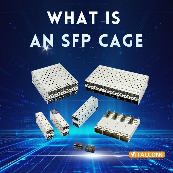
    If you've ever looked at the back of a network switch, a server, or a fiber-to-Ethernet media converter, you've seen them: a row of rectangular metal-framed slots, each about the size of two fingers side by side, waiting for a small modular plug to slide in. Those slots are SFP cages — and they are far more than simple metal boxes. Despite being one of the smallest components on a network board, the SFP cage directly affects your product's electromagnetic compliance, thermal performance, and module interoperability. Getting the wrong cage can mean failed FCC tests, overheating modules in the field, or modules that simply don't fit. In this article, we'll explain what an SFP cage is, how it works, the different types available, and why choosing the right one matters more than you might think. Definition: What Exactly Is an SFP Cage? An SFP cage (Small Form-factor Pluggable cage) is a passive electromechanical receptacle mounted on a printed circuit board (PCB) that serves as the housing for a pluggable optical or copper transceiver module. The cage provides: Mechanical retention for the SFP module, ensuring it stays firmly seated during vibration, thermal cycling, and cable handling Electromagnetic shielding that contains high-frequency emissions and prevents external interference Thermal conduction that transfers heat from the module to the PCB, chassis, or heatsink ESD protection through a grounded metal shell for safe hot-swap events Electrical interface routing — connecting the module's signals to the host PCB's differential pairs Key point: The SFP cage is a passive component — it contains no active electronics. However, its mechanical and electrical design has a profound impact on system-level performance. The SFP cage is defined by the SFP Multi-Source Agreement (MSA), a set of specifications developed jointly by transceiver manufacturers to ensure interoperability between modules and host systems. The MSA specifies mechanical dimensions, pin assignments, and electrical characteristics. A Brief History of the SFP Form Factor Era Form Factor Data Rate Key Innovation Early 2000s SFP 1.25 Gbps Replaced larger GBIC, 50% size reduction ~2006 SFP+ 10 Gbps Same footprint, 10× the speed ~2014 SFP28 25/28 Gbps Optimized for single-lane 25G Ethernet ~2013 QSFP+ 40 Gbps 4 channels, enhanced EMI ~2016 QSFP28 100 Gbps 4 × 25G channels ~2017 QSFP-DD 400 Gbps Double-density, 8 channels ~2019 SFP-DD 100 Gbps Dual-channel SFP The Anatomy of an SFP Cage 1. Cage Housing (Shell) The outer metal shell is typically made from phosphor bronze or beryllium copper, stamped and formed into a rectangular housing. Shell thickness is typically 0.3–0.4 mm. Some cages use a two-piece shell (top cover + bottom tray) for easier manufacturing; others are a one-piece drawn shell for superior EMI continuity. 2. EMI Fingers (Gasket Fingers) Spring-loaded metal fingers protrude inward from the cage walls. When a module is inserted, these fingers press against the module's metal housing, creating a continuous conductive seal. Standard cages have 4–6 EMI fingers per side; enhanced EMI cages (SFP+ and above) may have 8–12 per side. 3. Contact Pads (Signal Interface) The bottom of the cage features contact pads that mate with the SFP module's edge connector — typically gold over nickel (Au/Ni) plating with minimum 0.76 μm gold thickness. The standard 20-pin configuration includes signal pairs (TD+/TD-, RD+/RD-), power pins (VccT, VccR, GND), control signals (ModSel, LOS, TxFault, TxDisable), and I2C pins (SDA, SCL). 4. Module Detection Mechanism Most SFP cages include a module-absent (ModAbs) switch — a small spring-loaded lever that detects module insertion. When the module pushes the lever, the switch state changes, enabling hot-swap detection, module identification (via EEPROM), and link management. 5. Cage Leads (Mounting Terminals) Through-hole cages use metal pins soldered through the PCB (excellent mechanical strength). Surface-mount cages use flat tabs for reflow soldering (lower profile, automated assembly). Ground leads are critical — a well-designed cage will have dedicated ground pads around the entire perimeter. How Does an SFP Cage Work? Step by Step Module approach → EMI contact → Electrical mating → Module detection → Link establishment → Continuous operation → Hot removal Module approach: The module enters the cage opening. Internal alignment features guide the module into position. EMI contact: EMI fingers press against the module housing, establishing a conductive seal — before the electrical pins mate (make-first grounding). Electrical mating: The module's edge connector slides onto the cage's contact pads. Power is applied. Module detection: The ModAbs lever triggers the detection switch. The host reads the module EEPROM via I2C. Link establishment: The PHY negotiates the link (autonegotiation or fixed config). The module begins transmitting. Continuous operation: The cage maintains mechanical retention, EMI shielding, and thermal conduction. Hot removal: The user pulls the module. ModAbs detects removal, the host disables the PHY, and EMI fingers break after signal pins. SFP vs. SFP+ vs. QSFP: What's the Difference? Feature SFP SFP+ QSFP28 Max speed 1.25 Gbps 10 Gbps 100 Gbps Channels 1 1 4 Cage size 13 × 57 mm 13 × 57 mm 18 × 72 mm Power/port < 1 W 1–1.5 W 3.5–4.5 W EMI shielding Basic Enhanced Multi-channel MSA spec SFF-8074 SFF-8431 SFF-8665 Key application Access switches Enterprise / DC Core / spine Why the SFP Cage Matters More Than You Think EMI Compliance A poorly shielded cage can cause your product to fail FCC or CE radiated emission tests — potentially adding months of redesign and re-certification. The cage is often the single largest contributor to (or defense against) radiated emissions on the board. Module Interoperability Tolerances accumulate. A cage with tight internal dimensions may reject modules from certain vendors. A cage with loose dimensions may allow excessive play, causing intermittent contact failures. Fit-checking with modules from multiple vendors during design is essential. Thermal Throttling Modern SFP28 and QSFP28 modules operate at the thermal limit. If the cage doesn't conduct heat efficiently, the module's temperature sensor will trigger thermal shutdown — your link drops and throughput falls to zero. Reliability in Harsh Environments For industrial applications (factory automation, outdoor telecom, transportation), the cage must withstand wide temperature ranges (-40°C to +85°C), vibration and shock, humidity, and 500+ hot-swap cycles. Cages made from standard nylon may warp or become brittle under these conditions — LCP material is required. How to Choose an SFP Cage: Quick Decision Guide Your Requirement Recommended Cage Type 1G Ethernet, cost-sensitive Standard SFP, through-hole, basic EMI 10G Enterprise switch SFP+ with EMI fingers, surface-mount 25G Data-center leaf SFP28, enhanced EMI, thermal pad option 40G Aggregation QSFP+, multi-channel shielding 100G Core switch QSFP28, thermal cage with heatsink clip 400G Hyperscale QSFP-DD or OSFP with active cooling Industrial / outdoor Through-hole, LCP, -40 to +85°C rated Mixed 1G/10G deployment SFP+ cage (backward-compatible with SFP) About VITALCONN VITALCONN Electronics Technology is a professional manufacturer of SFP cages and other network interface connectors based in Shenzhen, China. With over 15 years of experience, we serve network equipment manufacturers, EMS providers, and connector distributors worldwide. Full SFP cage range: SFP, SFP+, SFP28, QSFP, QSFP+, QSFP28, QSFP-DD, OSFP EMI finger option: Standard and enhanced shielding versions Custom configurations: Non-standard port counts, branded bezels, special materials Certifications: ISO 9001, ISO 14001, RoHS, REACH, UL MOQ: 100 pieces for standard catalog items Need datasheets, S-parameters, or free samples? 📧 sales@vitalconn.com | 🌐 www.vitalconngroup.com / www.vitalconn.com  FAQ Q1: Is an SFP cage the same as an SFP module? No. The SFP cage is the receptacle permanently mounted on the PCB. The SFP module (transceiver) is the pluggable device you insert into the cage. The cage provides mechanical housing, EMI shielding, and the electrical interface; the module contains the active optical/electronic components. Q2: Can any SFP module work in any SFP cage? Generally yes, within the same speed class. However, minor dimensional tolerances between cage manufacturers mean that a fit-check is always recommended, especially if you need to support modules from multiple vendors. SFP+ modules require cages specifically rated for 10G operation. Q3: What material are SFP cages made from? The metal shell is typically phosphor bronze or beryllium copper with gold-over-nickel plating. The insulating body is typically LCP (Liquid Crystal Polymer) for high-temperature applications, or PBT/PA9T for standard applications. LCP offers superior dimensional stability at temperatures above 260°C. Q4: Do I need EMI fingers on my SFP cage? EMI fingers are strongly recommended for any design operating at 10 Gbps (SFP+) or above, and for any product that must pass FCC Class B or EN 55032 radiated emission limits. For 1G applications in controlled environments, a standard cage without EMI fingers may be sufficient — but verify through EMC testing. Q5: What does "hot swap" mean for an SFP cage? Hot swap means you can insert or remove an SFP module while the host system is powered on. The cage supports this by ensuring ground contact is made before signal pins (make-first) and broken after signal pins (break-last). The ModAbs switch alerts the host firmware to handle the event gracefully. Q6: How do I get S-parameter data for an SFP cage? Contact your cage manufacturer directly. Reputable suppliers like VITALCONN provide S-parameter (touchstone) files for their SFP cage products upon request. These files are essential for signal-integrity simulation in tools like ADS, HFSS, or HyperLynx. © 2026 VITALCONN Electronics Technology (Shenzhen) Co., Limited. All rights reserved. | www.vitalconngroup.com
    Read More

leave a message

leave a message
If you are interested in our products and want to know more details,please leave a message here,we will reply you as soon as we can.
submit

home

products

whatsApp

contact