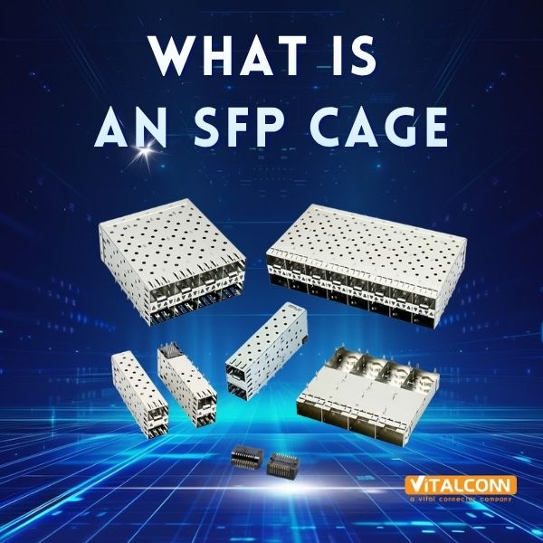
What Is an SFP Cage? Everything You Need to Know About Fiber Optic Transceiver Housings
Apr 27, 2026
If you've ever looked at the back of a network switch, a server, or a fiber-to-Ethernet media converter, you've seen them: a row of rectangular metal-framed slots, each about the size of two fingers side by side, waiting for a small modular plug to slide in. Those slots are SFP cages — and they are far more than simple metal boxes.
Despite being one of the smallest components on a network board, the SFP cage directly affects your product's electromagnetic compliance, thermal performance, and module interoperability. Getting the wrong cage can mean failed FCC tests, overheating modules in the field, or modules that simply don't fit.
In this article, we'll explain what an SFP cage is, how it works, the different types available, and why choosing the right one matters more than you might think.
Definition: What Exactly Is an SFP Cage?
An SFP cage (Small Form-factor Pluggable cage) is a passive electromechanical receptacle mounted on a printed circuit board (PCB) that serves as the housing for a pluggable optical or copper transceiver module. The cage provides:
Mechanical retention for the SFP module, ensuring it stays firmly seated during vibration, thermal cycling, and cable handling
Electromagnetic shielding that contains high-frequency emissions and prevents external interference
Thermal conduction that transfers heat from the module to the PCB, chassis, or heatsink
ESD protection through a grounded metal shell for safe hot-swap events
Electrical interface routing — connecting the module's signals to the host PCB's differential pairs
Key point: The SFP cage is a passive component — it contains no active electronics. However, its mechanical and electrical design has a profound impact on system-level performance.
The SFP cage is defined by the SFP Multi-Source Agreement (MSA), a set of specifications developed jointly by transceiver manufacturers to ensure interoperability between modules and host systems. The MSA specifies mechanical dimensions, pin assignments, and electrical characteristics.
A Brief History of the SFP Form Factor
Era
Form Factor
Data Rate
Key Innovation
Early 2000s
SFP
1.25 Gbps
Replaced larger GBIC, 50% size reduction
~2006
SFP+
10 Gbps
Same footprint, 10× the speed
~2014
SFP28
25/28 Gbps
Optimized for single-lane 25G Ethernet
~2013
QSFP+
40 Gbps
4 channels, enhanced EMI
~2016
QSFP28
100 Gbps
4 × 25G channels
~2017
QSFP-DD
400 Gbps
Double-density, 8 channels
~2019
SFP-DD
100 Gbps
Dual-channel SFP
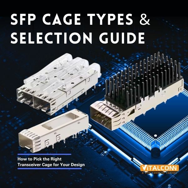
The Anatomy of an SFP Cage
1. Cage Housing (Shell)
The outer metal shell is typically made from phosphor bronze or beryllium copper, stamped and formed into a rectangular housing. Shell thickness is typically 0.3–0.4 mm. Some cages use a two-piece shell (top cover + bottom tray) for easier manufacturing; others are a one-piece drawn shell for superior EMI continuity.
2. EMI Fingers (Gasket Fingers)
Spring-loaded metal fingers protrude inward from the cage walls. When a module is inserted, these fingers press against the module's metal housing, creating a continuous conductive seal. Standard cages have 4–6 EMI fingers per side; enhanced EMI cages (SFP+ and above) may have 8–12 per side.
3. Contact Pads (Signal Interface)
The bottom of the cage features contact pads that mate with the SFP module's edge connector — typically gold over nickel (Au/Ni) plating with minimum 0.76 μm gold thickness. The standard 20-pin configuration includes signal pairs (TD+/TD-, RD+/RD-), power pins (VccT, VccR, GND), control signals (ModSel, LOS, TxFault, TxDisable), and I2C pins (SDA, SCL).
4. Module Detection Mechanism
Most SFP cages include a module-absent (ModAbs) switch — a small spring-loaded lever that detects module insertion. When the module pushes the lever, the switch state changes, enabling hot-swap detection, module identification (via EEPROM), and link management.
5. Cage Leads (Mounting Terminals)
Through-hole cages use metal pins soldered through the PCB (excellent mechanical strength). Surface-mount cages use flat tabs for reflow soldering (lower profile, automated assembly). Ground leads are critical — a well-designed cage will have dedicated ground pads around the entire perimeter.
How Does an SFP Cage Work? Step by Step
Module approach → EMI contact → Electrical mating → Module detection → Link establishment → Continuous operation → Hot removal
Module approach: The module enters the cage opening. Internal alignment features guide the module into position.
EMI contact: EMI fingers press against the module housing, establishing a conductive seal — before the electrical pins mate (make-first grounding).
Electrical mating: The module's edge connector slides onto the cage's contact pads. Power is applied.
Module detection: The ModAbs lever triggers the detection switch. The host reads the module EEPROM via I2C.
Link establishment: The PHY negotiates the link (autonegotiation or fixed config). The module begins transmitting.
Continuous operation: The cage maintains mechanical retention, EMI shielding, and thermal conduction.
Hot removal: The user pulls the module. ModAbs detects removal, the host disables the PHY, and EMI fingers break after signal pins.
SFP vs. SFP+ vs. QSFP: What's the Difference?
Feature
SFP
SFP+
QSFP28
Max speed
1.25 Gbps
10 Gbps
100 Gbps
Channels
1
1
4
Cage size
13 × 57 mm
13 × 57 mm
18 × 72 mm
Power/port
< 1 W
1–1.5 W
3.5–4.5 W
EMI shielding
Basic
Enhanced
Multi-channel
MSA spec
SFF-8074
SFF-8431
SFF-8665
Key application
Access switches
Enterprise / DC
Core / spine
Why the SFP Cage Matters More Than You Think
EMI Compliance
A poorly shielded cage can cause your product to fail FCC or CE radiated emission tests — potentially adding months of redesign and re-certification. The cage is often the single largest contributor to (or defense against) radiated emissions on the board.
Module Interoperability
Tolerances accumulate. A cage with tight internal dimensions may reject modules from certain vendors. A cage with loose dimensions may allow excessive play, causing intermittent contact failures. Fit-checking with modules from multiple vendors during design is essential.
Thermal Throttling
Modern SFP28 and QSFP28 modules operate at the thermal limit. If the cage doesn't conduct heat efficiently, the module's temperature sensor will trigger thermal shutdown — your link drops and throughput falls to zero.
Reliability in Harsh Environments
For industrial applications (factory automation, outdoor telecom, transportation), the cage must withstand wide temperature ranges (-40°C to +85°C), vibration and shock, humidity, and 500+ hot-swap cycles. Cages made from standard nylon may warp or become brittle under these conditions — LCP material is required.
How to Choose an SFP Cage: Quick Decision Guide
Your Requirement
Recommended Cage Type
1G Ethernet, cost-sensitive
Standard SFP, through-hole, basic EMI
10G Enterprise switch
SFP+ with EMI fingers, surface-mount
25G Data-center leaf
SFP28, enhanced EMI, thermal pad option
40G Aggregation
QSFP+, multi-channel shielding
100G Core switch
QSFP28, thermal cage with heatsink clip
400G Hyperscale
QSFP-DD or OSFP with active cooling
Industrial / outdoor
Through-hole, LCP, -40 to +85°C rated
Mixed 1G/10G deployment
SFP+ cage (backward-compatible with SFP)
About VITALCONN
VITALCONN Electronics Technology is a professional manufacturer of SFP cages and other network interface connectors based in Shenzhen, China. With over 15 years of experience, we serve network equipment manufacturers, EMS providers, and connector distributors worldwide.
Full SFP cage range: SFP, SFP+, SFP28, QSFP, QSFP+, QSFP28, QSFP-DD, OSFP
EMI finger option: Standard and enhanced shielding versions
Custom configurations: Non-standard port counts, branded bezels, special materials
Certifications: ISO 9001, ISO 14001, RoHS, REACH, UL
MOQ: 100 pieces for standard catalog items
Need datasheets, S-parameters, or free samples?
📧 sales@vitalconn.com | 🌐 www.vitalconngroup.com / www.vitalconn.com
FAQ
Q1: Is an SFP cage the same as an SFP module?
No. The SFP cage is the receptacle permanently mounted on the PCB. The SFP module (transceiver) is the pluggable device you insert into the cage. The cage provides mechanical housing, EMI shielding, and the electrical interface; the module contains the active optical/electronic components.
Q2: Can any SFP module work in any SFP cage?
Generally yes, within the same speed class. However, minor dimensional tolerances between cage manufacturers mean that a fit-check is always recommended, especially if you need to support modules from multiple vendors. SFP+ modules require cages specifically rated for 10G operation.
Q3: What material are SFP cages made from?
The metal shell is typically phosphor bronze or beryllium copper with gold-over-nickel plating. The insulating body is typically LCP (Liquid Crystal Polymer) for high-temperature applications, or PBT/PA9T for standard applications. LCP offers superior dimensional stability at temperatures above 260°C.
Q4: Do I need EMI fingers on my SFP cage?
EMI fingers are strongly recommended for any design operating at 10 Gbps (SFP+) or above, and for any product that must pass FCC Class B or EN 55032 radiated emission limits. For 1G applications in controlled environments, a standard cage without EMI fingers may be sufficient — but verify through EMC testing.
Q5: What does "hot swap" mean for an SFP cage?
Hot swap means you can insert or remove an SFP module while the host system is powered on. The cage supports this by ensuring ground contact is made before signal pins (make-first) and broken after signal pins (break-last). The ModAbs switch alerts the host firmware to handle the event gracefully.
Q6: How do I get S-parameter data for an SFP cage?
Contact your cage manufacturer directly. Reputable suppliers like VITALCONN provide S-parameter (touchstone) files for their SFP cage products upon request. These files are essential for signal-integrity simulation in tools like ADS, HFSS, or HyperLynx.
© 2026 VITALCONN Electronics Technology (Shenzhen) Co., Limited. All rights reserved. | www.vitalconngroup.com
Read More


 IPv6 network supported