Leave A Message
If you are interested in our products and want to know more details,please leave a message here,we will reply you as soon as we can.
submit

Blog

Home

Blog

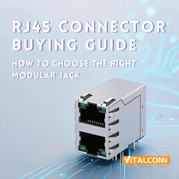
  • The Ultimate Guide to RJ45 Connectors (2026)
    The Ultimate Guide to RJ45 Connectors (2026)
    Jul 07, 2026
    The RJ45 connector is the most widely deployed networking connector on Earth. Since its standardization in IEC 60603-7, it has carried data across billions of Ethernet links, from office desktops to factory floors, data centers, and 5G base stations. Despite the rise of fiber optics, the RJ45 remains irreplaceable for the last 100 meters of copper connectivity, and it is evolving to support speeds up to 10 Gigabits per second and power delivery up to 90 watts (PoE++). This guide covers everything an engineer, procurement manager, or product designer needs to know about RJ45 connectors in 2026. What Is an RJ45 Connector? An RJ45 (Registered Jack 45) is an 8-position, 8-contact (8P8C) modular connector used primarily for Ethernet networking. It follows the IEC 60603-7 standard and supports twisted-pair copper cabling (Cat5e through Cat8). The connector consists of a plastic housing with 8 gold-plated contact pins, a spring-loaded latch for retention, and optionally integrated magnetic components (transformers, common-mode chokes) for signal isolation and PoE support. Brief History 1970s: RJ45 originally developed by Bell Labs for telephone wiring, adapted from the RJ11/RJ14 family 1983: IEEE 802.3 adopted RJ45 for 10Base-T Ethernet at 10 Mbps over Cat3 cable 1995: IEEE 802.3u brought 100Base-TX Fast Ethernet at 100 Mbps over Cat5 1999: IEEE 802.3ab introduced 1000Base-T Gigabit Ethernet at 1 Gbps over Cat5e, requiring all 4 pairs 2006: IEEE 802.3an enabled 10GBase-T at 10 Gbps over Cat6a/Cat7, demanding tighter crosstalk control 2018: IEEE 802.3bt delivered PoE++ Type 3 and Type 4, delivering up to 90W over RJ45 RJ45 Connector Anatomy Component Function Material Housing Mechanical protection and latch retention High-temperature thermoplastic (UL94V-0) Contact pins (8×) Electrical connection to cable conductors Phosphor bronze, gold-plated (flash to 50μ"") Latch (tab) Click-in retention in RJ45 jack Spring steel or integrated plastic Strain relief (optional) Prevents cable pull-out damage Metal or plastic boot Magnetic module (ICM only) Signal isolation, PoE, common-mode rejection Ferrite cores + copper wire LED indicators (optional) Link/activity status Green/Amber SMD LEDs EMI shield (optional) Reduces electromagnetic emissions Stamped metal shell (nickel/copper) RJ45 Connector Types: Complete Classification RJ45 connectors come in a wide variety of configurations. Understanding these types is critical for selecting the right part for your design. By Port Configuration Type Description Typical Application 1×1 (Single Port) One RJ45 jack in a single housing Consumer routers, IP cameras, basic NICs 1×N (Ganged Single-Row) Multiple ports side-by-side in one row Switches, hubs, patch panels 2×N (Stacked Dual-Row) Two rows of ports stacked vertically High-density switches, server motherboards Combo (RJ45 + USB/SFP) RJ45 combined with other connector types Industrial gateways, modular equipment By Magnetic Integration Type Magnetics Use Case Non-Magnetic RJ45 No internal transformers; external magnetics required on PCB Cost-sensitive designs with discrete magnetics ICM (Integrated Connector with Magnetics) Transformers + common-mode chokes built into connector Most common; simplifies PCB design, ensures compliance Magnetic Modular Jack Full magnetic module with PoE center taps PoE switches, industrial Ethernet, telecom equipment 💡 Tip: VITALCONN’s ICM RJ45 product line covers 163 models from 10/100Base-T to 10GBase-T, with PoE support from IEEE 802.3af (15.4W) to 802.3bt Type 4 (90W). By Mounting Type Mounting Installation Best For DIP (Through-Hole) Pins soldered through PCB holes High-reliability, vibration-resistant designs SMT (Surface Mount) Pads soldered on PCB surface High-volume automated production, compact designs Press-Fit (Compliant Pin) Pins press into plated PCB holes, no solder Lead-free processes, rework-free assembly By Tab Orientation and Shielding Tab Down (Standard): The most common orientation; tab faces downward when plugged in Tab Up: Tab faces upward; used when PCB orientation is inverted Tab Offset: Tab is offset to the side; used in ultra-low-profile designs Unshielded: No metal shield; suitable for low-speed (10/100M) or minimal EMI environments Shielded: Full metal enclosure; required for Gigabit and 10G applications to meet FCC/CISPR emissions limits Shielded + EMI Gasket: Metal shell plus conductive gasket for 360° grounding; essential for 10GBase-T and high-density switches Key RJ45 Specifications You Must Know Speed and Standards Standard Speed Cable Pairs Used Max Distance 10Base-T 10 Mbps Cat3+ 2 100m 100Base-TX 100 Mbps Cat5+ 2 100m 1000Base-T 1 Gbps Cat5e+ 4 100m 2.5GBase-T 2.5 Gbps Cat5e+ 4 100m 5GBase-T 5 Gbps Cat6+ 4 100m 10GBase-T 10 Gbps Cat6a+ 4 100m (Cat6a) PoE (Power over Ethernet) Support PoE Standard Type Max Power (PSE) Max Power (PD) Voltage IEEE 802.3af Type 1 (PoE) 15.4W 12.95W 44–57V DC IEEE 802.3at Type 2 (PoE+) 30W 25.5W 50–57V DC IEEE 802.3bt Type 3 (PoE++) 60W 51W 50–57V DC IEEE 802.3bt Type 4 (PoE++) 90W 71W 50–57V DC For PoE applications, the RJ45 connector must have a magnetic module with center-tapped transformers. The center tap carries DC power, so the transformer must handle the full PoE current without saturation. VITALCONN’s PoE-capable ICM RJ45 connectors support up to 90W (Type 4) with thermal management to prevent core saturation at high current. Gold Plating Thickness Plating Thickness Application Flash gold 0.05–0.1 μm Low-cost consumer, low insertion cycles Standard gold 0.4–0.8 μm (15–30μ"") General networking equipment Thick gold 1.0–1.27 μm (40–50μ"") Industrial, high-reliability, 5,000+ cycles Isolation Voltage and Operating Temperature Standard isolation: 1500 VAC RMS minimum (per IEC 60603-7) Industrial grade: 1500–3000 VAC High-isolation: 3000–5000 VAC (medical and industrial applications) Commercial temperature: 0°C to +70°C Extended temperature: -20°C to +85°C Industrial temperature: -40°C to +85°C How to Choose the Right RJ45 Connector: Step-by-Step Define your speed requirement: Determine the required data rate (10/100M, 1G, 2.5G, 5G, or 10G). This sets the minimum cable category and connector performance class. Determine PoE requirements: Determine if PoE is needed and what type (af/at/bt Type 3 or 4). This determines whether you need center-tapped magnetics and what current rating is required. Choose magnetic integration: Choose between ICM (integrated magnetics) or non-magnetic with external magnetics. ICM simplifies design and ensures compliance; external magnetics offer design flexibility. Select port configuration: Determine single port (1×1), ganged (1×N), or stacked (2×N) based on your port count and PCB space. Select mounting type: Choose DIP for high reliability and reworkability, SMT for automated high-volume production, or Press-Fit for lead-free, solder-free assembly. Select gold plating: Choose gold plating thickness based on expected insertion cycles and environmental conditions. Consider shielding and environment: For Gigabit and above, use shielded connectors with EMI gaskets. For industrial environments, choose -40°C rated parts. Verify compliance: Ensure the connector is UL recognized and RoHS compliant. For medical devices, check IEC 60601 isolation requirements. Common RJ45 Design Mistakes (and How to Avoid Them) Mistake 1: Ignoring PoE Thermal Management At 90W PoE++, each pair carries nearly 1A of DC current. If the magnetic transformer core is undersized, it will saturate, causing signal degradation and potential fire risk. Always verify that the ICM is rated for the full PoE power level, not just the signal speed. Mistake 2: Using Unshielded Connectors for 10GBase-T 10GBase-T operates at frequencies up to 500 MHz. Unshielded RJ45 connectors cannot contain these emissions, leading to FCC/CISPR test failures. Always use shielded connectors with 360-degree EMI grounding for 10G applications. Mistake 3: Mismatched Cable Category and Connector Class A Cat6a connector on a Cat5e cable (or vice versa) creates an impedance mismatch that causes reflections and signal degradation. Always match the connector performance class to the cable category. Mistake 4: Overlooking Insertion and Return Loss Cheap RJ45 connectors often have poor impedance matching, resulting in return loss values that fail IEEE 802.3 limits. Always request S-parameter data from the manufacturer and verify compliance at your target speed. Mistake 5: Choosing Gold Plating Too Thin for Industrial Use Flash gold (0.05 μm) may suffice for consumer devices with 50 insertion cycles, but industrial applications requiring 5,000+ cycles need at least 0.4 μm (15 microinches) of gold. Insufficient plating leads to contact oxidation and intermittent connections. ⚠️ Important: At 90W PoE++ (IEEE 802.3bt Type 4), each twisted pair carries approximately 0.96A of DC current. Using an ICM not rated for this current will cause transformer core saturation, signal degradation, and potential fire risk. Always verify the PoE current rating, not just the signal speed rating. VITALCONN RJ45 Connector Solutions VITALCONN manufactures 163 ICM RJ45 models and additional non-magnetic RJ45 variants, covering the full range of speeds, port configurations, and mounting types. Our products are ISO 9001 certified and serve customers in networking, industrial automation, and consumer electronics globally. Key Differentiators Differentiator Details Full Speed Range 10/100Base-T through 10GBase-T, including 2.5G and 5G Complete PoE Support IEEE 802.3af (15.4W) through 802.3bt Type 4 (90W) All Mounting Types DIP, SMT, and Press-Fit available Stacked Configurations 2×1 through 2×8 stacked RJ45 with shared or independent magnetics Customizable Gold Plating Flash to 50 microinches, tailored to customer requirements EMI Shielding Full metal shield with 360° grounding and optional EMI gaskets Industrial Temperature -40°C to +85°C rated components for harsh environments ARP Cross-Reference Platform 26 pin-to-pin replacement records for TE, Molex, Pulse, BelFuse, and more Featured Products Stacked Magnetic RJ45 (2×N): Available in 2×1 through 2×8 configurations, supporting 10/100Mbps and 1G with PoE. Cat6 compliant, DIP mounting, with EMI shielding options. 10G PoE++ ICM RJ45: Single-port ICM RJ45 with 10GBase-T support, PoE++ Type 4 (90W), SMT mounting, -40°C to +85°C. 1×N Ganged RJ45: Compact 1×N RJ45 for high-density switches with shared magnetics module and LED indicators. ARP: Alternative Replacement Platform VITALCONN’s ARP platform provides 123 pin-to-pin replacement records across 5 product categories. For RJ45 specifically, we offer 26 cross-reference replacements covering 11 different competitor brands, including Pulse Electronics, BelFuse, TE Connectivity, Molex, Amphenol, and more. This means you can often replace an EOL or shortage-affected part with a VITALCONN equivalent without redesigning your PCB. 💡 Tip: ARP cross-reference replacements offer 30–40% cost reduction vs. original parts, 2–4 week lead time (vs. 12–24 weeks for many competitors), and pin-to-pin mechanical and electrical compatibility. Contact sales@vitalconn.com with your current part number for a match. Frequently Asked Questions (FAQ) What does RJ45 stand for? RJ45 stands for Registered Jack 45. It is an 8-position, 8-contact (8P8C) modular connector standardized under IEC 60603-7. Despite the “registered jack” name, it is now primarily used for Ethernet networking rather than telephone wiring. What is the difference between RJ45 and RJ11? RJ45 has 8 contacts (8P8C) and is used for Ethernet; RJ11 has 6 positions with 2 or 4 contacts (6P2C/6P4C) and is used for telephone lines. RJ45 is physically larger than RJ11. An RJ11 plug can fit into an RJ45 jack, but this is not recommended as it can damage the contacts. Do I need a magnetic (ICM) RJ45 or a non-magnetic one? If your PCB has discrete magnetics already laid out, you can use a non-magnetic RJ45. However, most modern designs use ICM because it simplifies PCB layout, ensures IEEE compliance, and provides better signal integrity. ICM is essentially mandatory for PoE applications because the center-tapped transformer is needed to inject DC power. Can RJ45 support 10 Gigabit Ethernet? Yes. 10GBase-T (IEEE 802.3an) operates over RJ45 connectors with Cat6a or Cat7 cabling at distances up to 100 meters. However, 10G requires shielded connectors with tight impedance control (100 ± 15 ohms) and low crosstalk. VITALCONN offers 10G-rated ICM RJ45 connectors with full metal shielding and EMI gaskets. What PoE power levels can RJ45 handle? RJ45 connectors with appropriate magnetics can support the full range of PoE standards: IEEE 802.3af (15.4W), 802.3at (30W), and 802.3bt Type 3 (60W) and Type 4 (90W). At 90W, each twisted pair carries approximately 0.96A of DC current, requiring magnetics designed to handle this current without core saturation. What is the maximum number of insertion cycles for RJ45? Standard RJ45 connectors are rated for 750 insertion cycles minimum (per IEC 60603-7). Industrial-grade connectors with thicker gold plating (30–50 microinches) can achieve 5,000+ cycles. VITALCONN offers gold plating up to 50 microinches for high-cycle applications. How do I know if a VITALCONN RJ45 can replace my current part? VITALCONN’s ARP (Alternative Replacement Platform) provides 26 pin-to-pin RJ45 cross-reference records covering Pulse, BelFuse, TE, Molex, Amphenol, and 6 other brands. Contact sales@vitalconn.com with your current part number, and we will identify the equivalent VITALCONN model, typically with 30–40% cost savings and faster lead times. Ready to Find the Right RJ45 Connector? Explore VITALCONN’s 163+ ICM RJ45 models—10/100M to 10G, PoE to 90W, pin-to-pin compatible with Pulse, BelFuse, TE, and Molex—or request free samples and ARP cross-reference support for your next project. Explore RJ45 Connectors Request Samples
    Read More
  • SFP Cage EMI Shielding: Why It Matters for 400G and 800G Data Centers (2026)
    SFP Cage EMI Shielding: Why It Matters for 400G and 800G Data Centers (2026)
    Jul 01, 2026
    As data center speeds scale from 100G to 400G and 800G, electromagnetic interference (EMI) shielding in SFP cage connectors becomes a make-or-break design consideration. At 25 Gbps per lane and above, even minor EMI leakage can degrade signal integrity, cause bit errors, and result in compliance failures. This guide explains why EMI shielding matters, how it works, and what to look for when selecting SFP cages for high-speed applications. What Is EMI and Why Does It Matter in SFP Cages? Electromagnetic interference (EMI) is unwanted electromagnetic energy that disrupts the normal operation of electronic circuits. In SFP cage assemblies, EMI originates from two primary sources: Radiated emissions: High-speed differential signals (25G, 50G, 100G per lane) radiate electromagnetic energy through the cage openings Crosstalk: Adjacent ports in multi-port cage configurations can couple noise between channels At 10Gbps and below, the impact of EMI leakage through SFP cages is manageable. But at 25Gbps per lane (QSFP28 and above), the signal wavelengths are short enough that cage openings become efficient antennas, making robust EMI shielding essential. How SFP Cage EMI Shielding Works Effective SFP cage EMI shielding creates a continuous Faraday cage around the transceiver module. Key design elements include: 1. EMI Gaskets (Spring Fingers) Beryllium copper (BeCu) EMI gaskets and spring fingers make 360° contact between the cage body and the transceiver module's metal housing. This continuous grounding path prevents EMI from leaking through gaps between the module and cage. VITALCONN SFP cages use BeCu spring fingers that achieve crosstalk isolation below -40 dB at 10 GHz, among the best performance available in the industry. 2. Cage Body Design The cage body itself acts as the primary EMI shield. Critical design factors include: Material thickness — thicker walls provide better shielding but increase cost Seam design — overlapping seams minimize leakage Port divider walls — metal barriers between adjacent ports reduce crosstalk 3. PCB-Level Grounding The EMI shield is only as good as its grounding connection to the PCB. Press-fit cages inherently provide better grounding than solder cages because: Each press-fit pin creates a gas-tight, low-impedance ground connection Press-fit pins maintain consistent contact force over the product lifetime Multiple ground pins distribute ground current evenly, reducing ground plane noise EMI Shielding Requirements by Data Rate Data Rate Lanes Form Factor EMI Shielding Level Cage Design Considerations 1G 1 SFP Basic Simple cage, minimal gasketing 10G 1 SFP+ Moderate EMI gasket recommended 25G 1 SFP28 High 360° BeCu gasket required 40G 4×10G QSFP+ High Port dividers + gaskets 100G 4×25G QSFP28 Very High Full shielding + port dividers 400G 8×50G QSFP-DD Critical Full shielding + dividers + thermal 800G 8×100G OSFP Critical Full shielding + dividers + active cooling Why EMI Shielding Becomes Critical at 400G/800G At 400G (QSFP-DD) and 800G (OSFP), the EMI challenge intensifies for three reasons: Higher per-lane speed: Each lane carries 50G or 100G, producing proportionally stronger radiated emissions More lanes = more openings: 8-lane cages have more internal gaps and seam paths where EMI can leak Thermal-EMI trade-off: The heatsink required to cool 400G/800G modules adds thermal design complexity that must not compromise EMI integrity VITALCONN SFP Cage EMI Shielding Solutions VITALCONN SFP cages are engineered for the highest EMI shielding performance: BeCu 360° EMI Gaskets All VITALCONN SFP28, QSFP28, QSFP-DD, and OSFP cages feature beryllium copper spring fingers that provide continuous 360° grounding contact. Key performance metrics: Crosstalk isolation: <-40 dB at 10 GHz Contact resistance: <10 mΩ per finger Spring force: maintained over 10,000+ insertion cycles 💡 Tip: VITALCONN's BeCu spring fingers achieve the industry's best crosstalk isolation at <-40 dB, giving designers 5–10 dB of additional margin over competing solutions for compliance with FCC Part 15 and CISPR 32 emission limits. Integrated Port Dividers Multi-port cages include metal port divider walls that isolate adjacent channels, preventing inter-port crosstalk in high-density switch designs. Thermal-EMI Integrated Design VITALCONN cages with integrated heatsinks use a top-vent design that provides both thermal airflow and EMI containment. The heatsink fins are electrically bonded to the cage body, maintaining shielding integrity while allowing convective cooling. Measuring SFP Cage EMI Performance When evaluating SFP cage EMI performance, look for these test results: Crosstalk: Near-end crosstalk (NEXT) at the target data rate Emissions: FCC Part 15 Class A (commercial) and Class B (residential) Signal integrity: Insertion loss and return loss through the cage assembly VITALCONN provides EMI test data for all SFP cage models, enabling designers to validate compliance before committing to a design. SFP Cage Cross-Reference for High-Speed Applications VITALCONN offers pin-to-pin SFP cage replacements optimized for EMI performance: VITALCONN P/N Competitor P/N Brand Speed Ports EMI Feature S2N32H1000NA4 2291634-2 TE QSFP28 (100G) 2×1 BeCu gasket + divider S2N32H0206NA4 2227303-2 TE QSFP28 (100G) 2×6 Full EMI shield S1N3A23000CA4 747548220 Molex SFP28 (25G) 1×1 BeCu gasket + heatsink S2N3D23004BA4 1-2149490-5 TE QSFP-DD (400G) 1×1 Full EMI + thermal ⚠️ Important: At 400G (QSFP-DD) and 800G (OSFP), full EMI shielding is not optional. Multi-port cages without proper port dividers and 360° BeCu gaskets will fail FCC/CISPR emission compliance. Always verify EMI test data before finalizing your BOM. Frequently Asked Questions (FAQ) Do I need EMI shielding for 10G SFP+ cages? EMI gaskets are recommended for 10G SFP+ cages, especially in multi-port configurations. While some 10G designs may work without gaskets in low-density setups, the cost of adding EMI shielding is minimal compared to the risk of EMI-related signal integrity issues. Can I add EMI shielding to an existing SFP cage design? EMI gaskets can sometimes be retrofitted, but the most effective approach is to select a cage designed with integrated EMI shielding from the start. Retrofit gaskets may not achieve 360° contact and can interfere with module insertion. How does heatsink design affect EMI shielding? A properly designed heatsink is electrically bonded to the cage body and does not compromise EMI shielding. However, poorly designed heatsinks with gaps or floating sections can create EMI leakage paths. VITALCONN's integrated heatsink designs maintain full EMI integrity while providing thermal management. Ready to Optimize Your EMI Shielding Design? Explore VITALCONN's full range of EMI-shielded SFP cages—pin-to-pin compatible with TE and Molex, 30–40% cost savings, 2–4 week lead times—or request free samples and EMI test data for your next project. Explore EMI SFP Cages Request Samples
    Read More
  • Push-Push vs Push-Pull Card Socket: Which One Should You Choose? (2026)
    Push-Push vs Push-Pull Card Socket: Which One Should You Choose? (2026)
    Jun 29, 2026
    Card socket connectors come in two primary ejection mechanisms: push-push and push-pull. While both serve the same fundamental purpose—holding a SIM, Micro SD, or SD card securely in place—their user experience, reliability, and mechanical design differ significantly. This guide explains the differences and helps you select the right mechanism for your device. What Is a Push-Push Card Socket? A push-push card socket uses a spring-loaded mechanism. The user inserts the card with a push, and a latch locks it in place. To eject, the user pushes the card again, which releases the latch and the spring pops the card out partially for easy removal. This mechanism is familiar to most consumers—it's the same system used in camera SD card slots and smartphone SIM trays. What Is a Push-Pull Card Socket? A push-pull card socket has no ejection mechanism. The user inserts the card by pushing it in, and removes it by pulling it out directly. The card is held in place by friction from the contact beams inside the socket. This simpler design is common in industrial and M2M (machine-to-machine) applications where the card is inserted once and rarely removed. Push-Push vs Push-Pull: Detailed Comparison Feature Push-Push Push-Pull Insertion Push in (auto-latch) Push in (friction hold) Ejection Push again (spring ejects card) Pull out manually User experience Intuitive, one-handed operation Requires grip on card edge Card retention Mechanical latch (very secure) Friction only (less secure) Vibration resistance Excellent (latch prevents ejection) Moderate (card can creep out) Profile height Typically taller (spring mechanism) Typically shorter (simpler) Part count More internal components Fewer internal components Cost Slightly higher Slightly lower Typical insertion cycles 5,000–10,000 5,000–10,000 Best for Consumer devices, frequent card swap Industrial, set-and-forget When Should You Choose Push-Push? Push-push is the right choice when: End users will swap cards regularly (smartphones, cameras, consumer electronics) One-handed card insertion/ejection is important for the user experience The device will be exposed to vibration or shock (automotive, portable devices) You need the card to stay securely locked in place without any risk of accidental ejection The card slot is recessed, making it difficult to grip the card for pull-out When Should You Choose Push-Pull? Push-pull is the right choice when: The card is inserted once during manufacturing and rarely or never removed (IoT devices, industrial gateways) You need the lowest possible profile height (push-pull sockets can be as thin as 1.13 mm) Cost optimization is a primary concern (fewer internal components) The device is in a controlled environment with minimal vibration Space constraints make the push-push spring mechanism too tall Profile Height Comparison: Which Mechanism Is Slimmer? A common misconception is that push-pull is always slimmer than push-push. In reality, the height difference depends on the specific model: Card Type Mechanism Height Range Thinnest Available Nano SIM Push-Push H1.25~2.5 mm H1.25 mm Nano SIM Push-Pull H1.13~2.0 mm H1.13 mm Micro SIM Push-Push H1.65~3.0 mm H1.65 mm Micro SD Push-Push H1.25~2.8 mm H1.25 mm Micro SD Push-Pull H1.13~2.5 mm H1.13 mm SD Card Push-Push H2.5~5.0 mm H2.5 mm For ultra-slim designs (H<1.5 mm), push-pull is typically the only option. For heights above 1.5 mm, push-push is available and often preferred for its superior retention. ⚠️ Important: Push-pull sockets rated below H1.25 mm are exclusively friction-hold designs. If your application involves any vibration, verify the retention force specification—friction-only retention can allow the card to creep out under sustained shock. Card Socket Cross-Reference: VITALCONN Replacements for Molex and JAE VITALCONN offers push-push and push-pull card socket replacements compatible with Molex, JAE, and other major brands: VITALCONN P/N Competitor P/N Brand Card Type Mechanism Height VTC102016832E1 SF72S006VBDR2500 JAE Nano SIM Push-Push H1.25 mm VTC102016832E2 105162-0001 Molex Nano SIM Push-Push H2.5 mm VTC402013832E1 5039600695 Molex Micro SIM Push-Push H1.65 mm C102316832E1 ST11S008V4HR2000 JAE Micro SD Push-Push H1.25 mm 💡 Tip: The C102316832E1 is VITALCONN's flagship Micro SD push-push socket: an ultra-thin 1.25 mm profile design that is pin-to-pin compatible with JAE ST11S008V4HR2000, priced at approximately 70% of the JAE part with 2–4 week lead time. Frequently Asked Questions (FAQ) Is push-push more reliable than push-pull? Both mechanisms can achieve 5,000+ insertion cycles. However, push-push provides more secure card retention thanks to the mechanical latch. In high-vibration environments, push-push is clearly superior because the latch prevents the card from creeping out under sustained vibration. Can a push-pull socket be used in a consumer device? It can, but it's not ideal. Consumer users expect the push-push ejection experience. A push-pull socket in a consumer device may lead to user frustration, especially if the card is difficult to grip for removal. Push-pull is better suited for industrial applications where the card is inserted once. What is the thinnest Micro SD socket available? The thinnest Micro SD sockets are approximately 1.13 mm in profile height. These are push-pull type. The thinnest push-push Micro SD sockets are approximately 1.25 mm. VITALCONN offers both types across its card socket product line. Ready to Find the Right Card Socket? Explore VITALCONN's full range of push-push and push-pull card sockets—pin-to-pin compatible with Molex and JAE, 30% cost savings, 2–4 week lead times—or request free samples for your next project. Explore Card Sockets Request Samples
    Read More
  • Press-Fit vs Solder: PCB Assembly Guide for Connector Mounting (2026)
    Press-Fit vs Solder: PCB Assembly Guide for Connector Mounting (2026)
    Jun 26, 2026
    When mounting connectors on a printed circuit board, engineers have two primary options: press-fit (also called compliant pin or press-in) and traditional solder mounting. While solder has been the default for decades, press-fit technology has become the preferred choice for high-reliability applications—especially in data center, telecommunications, and automotive electronics. This guide explains the differences, advantages, and selection criteria for each method. What Is Press-Fit Mounting? Press-fit mounting uses specially designed compliant pins that deform elastically when pressed into plated through-holes on the PCB. The pins create a gas-tight, cold-welded connection without any solder. The compliant section of the pin is typically shaped like an eye, hourglass, or multiple contact bands that maintain constant outward force against the through-hole barrel. What Is Solder Mounting? Solder mounting uses through-hole soldering (wave soldering or selective soldering) to create a metallurgical bond between the connector pins and the PCB. The solder joint provides both the electrical connection and mechanical retention. Solder mounting has been the industry standard for decades and is still widely used for cost-sensitive applications. Press-Fit vs Solder: Head-to-Head Comparison Parameter Press-Fit Solder Connection type Cold-welded gas-tight Metallurgical solder joint Process temperature Room temperature (no heat) 240–260°C (reflow/wave) FIT (Failures in Time) 0.1–1 per billion hours 3–30 per billion hours Reliability 10–30× higher than solder Baseline Thermal cycling resistance Excellent (flexible pin compensates) Moderate (solder cracks possible) Assembly process Press-in only (one step) Insert → wave solder → inspect (multi-step) Rework capability Not reworkable (pin deformation) Reworkable with desoldering tools PCB design Requires specific hole sizes (0.45–0.55mm) More flexible hole size range Initial cost Slightly higher per connector Lower per connector Total assembly cost Lower (fewer process steps) Higher (soldering + inspection) RoHS compliance Inherently lead-free Requires lead-free solder alloys Why Press-Fit Is 10–30× More Reliable Than Solder The dramatic reliability difference comes down to the physics of each connection: Press-fit pins maintain a constant spring force against the through-hole barrel, creating a gas-tight connection that resists oxidation and corrosion. The compliant pin flexes with thermal expansion and contraction, preventing stress accumulation. Solder joints, by contrast, are rigid. During thermal cycling, the different coefficients of thermal expansion (CTE) between the connector, solder, and PCB create mechanical stress. Over thousands of cycles, this stress can cause solder joint cracks—the most common failure mode in through-hole soldered connectors. Real-World FIT Value Comparison Metric Press-Fit Solder Improvement Factor FIT value (typical) 0.5 8.0 16× Thermal cycle life (-40°C to +125°C) >2,000 cycles 500–1,000 cycles 2–4× Vibration resistance Excellent Good Significant Drop/shock resistance Excellent Moderate Significant When Should You Choose Press-Fit? Press-fit is the recommended choice when: Your application requires high reliability (data center, telecom, automotive, aerospace) The product will experience significant thermal cycling (outdoor equipment, industrial) You want to eliminate the wave soldering step and reduce assembly cost You need to meet stringent DPPM targets (<300 PPM) Your design uses high-density, multi-port connectors (SFP cages, DIN connectors) When Is Solder Still Appropriate? Solder mounting remains a valid choice when: The connector is low-pin-count and cost is the primary driver Your PCB assembly line does not have press-fit insertion equipment Rework or field repair capability is required The application has minimal thermal cycling and vibration exposure SFP Cage: The Strongest Case for Press-Fit SFP cage connectors are perhaps the most compelling application for press-fit mounting. Here's why: Pin count: High port density—Multi-port SFP cages (2×1 to 2×8) have 40–80+ through-hole pins per cage. A single solder defect on any pin can cause a port failure. Mission-critical: SFP cages are used in switches and servers that must operate 24/7 for 5–10+ years. Press-fit eliminates solder joint fatigue as a failure mode. Hot-plug stress: SFP modules are hot-pluggable, creating repeated mechanical stress on the cage. Press-fit's superior vibration resistance is essential. 💡 Tip: VITALCONN offers 89 press-fit SFP cage models covering SFP, SFP+, SFP28, QSFP+, QSFP28, QSFP-DD, and OSFP form factors—the broadest selection in the industry. Press-Fit SFP Cage Cross-Reference: Replacing TE and Molex VITALCONN provides press-fit SFP cage replacements that are pin-to-pin compatible with TE Connectivity and Molex parts: VITALCONN P/N Competitor P/N Brand Form Factor Ports S2N3104800NA4 2007215-1 TE SFP+ 1×1 S2N3122055NA4 2149730-1 TE SFP+ w/ EMI 1×1 S2N32H0206NA4 2227303-2 TE QSFP28 2×6 S2N3400556NA4 74441-0001 Molex SFP+ 1×1 S1N3A23000CA4 747548220 Molex SFP28 w/ Heatsink 1×1 All VITALCONN press-fit SFP cages offer 30–40% cost savings over TE/Molex equivalents with 2–4 week lead times. How to Specify Press-Fit Connectors in Your Design When designing with press-fit connectors, pay attention to these PCB requirements: Hole size: Follow the connector manufacturer's recommended hole size and tolerance (typically ±0.05 mm) Plating: Ensure adequate copper thickness (≥25 μm) in the through-hole barrels Clearance: Maintain minimum 2 mm clearance around press-fit holes for insertion tool access Insertion force: Use press-fit insertion tools with controlled force (typically 50–150 N per pin) Frequently Asked Questions (FAQ) Can press-fit pins be reworked if damaged? Press-fit pins cannot be re-soldered or re-inserted once the compliant section has been deformed. If a press-fit connection fails, the typical repair is to replace the entire connector or use a modified solder repair process. This is why press-fit is best suited for applications where field rework is not expected. Does press-fit work with double-sided PCBs? Yes. Press-fit connections are compatible with multi-layer PCBs. The key requirement is that the through-hole plating meets the connector manufacturer's specifications for barrel thickness and surface finish (typically HASL, ENIG, or OSP). What is the typical insertion force for press-fit SFP cages? Press-fit insertion force depends on the number of pins. A typical 1×1 SFP cage requires approximately 50–80 N of insertion force. Multi-port cages (2×4, 2×6) may require 200–400 N. Always use the manufacturer's recommended insertion tool to ensure uniform pin deformation. Ready to Upgrade to Press-Fit SFP Cages? Explore VITALCONN's 89 press-fit SFP cage models—pin-to-pin compatible with TE and Molex, 30–40% cost savings, 2–4 week lead times—or request free samples for your next project. Explore Press-Fit SFP Cages Request Samples
    Read More
  • Micro SD Card Speed Class Guide: Class 10 to U3 to V30 (2026)
    Micro SD Card Speed Class Guide: Class 10 to U3 to V30 (2026)
    Jun 24, 2026
    Selecting the right Micro SD card for your device requires understanding a confusing array of speed class labels—Class 10, U1, U3, V10, V30, A1, A2, and more. This guide explains each speed class, what it means for real-world performance, and how to choose the right Micro SD card socket connector for your application. Why Micro SD Speed Classes Matter The speed class on a Micro SD card indicates its minimum sequential write speed—the guaranteed floor performance, not the peak. This distinction is critical because a card labeled "100 MB/s read" may only sustain 10 MB/s writes, which could cause dropped frames in video recording or data loss in IoT logging applications. Micro SD Speed Class Comparison Table Speed Class Symbol Min Sequential Write Typical Use Case SD Specification Class 2 C2 2 MB/s Standard definition video SD 2.0 Class 4 C4 4 MB/s SD video, basic photo SD 2.0 Class 6 C6 6 MB/s HD video (720p) SD 2.0 Class 10 C10 10 MB/s Full HD video (1080p) SD 3.0 U1 (UHS-I) U1 10 MB/s Full HD video, general use SD 3.01 U3 (UHS-I) U3 30 MB/s 4K video (UHD) SD 4.0 V10 (Video) V10 10 MB/s Full HD video SD 5.0 V30 (Video) V30 30 MB/s 4K UHD video SD 5.0 V60 (Video) V60 60 MB/s 8K video, high-bitrate 4K SD 6.0 V90 (Video) V90 90 MB/s 8K video, professional cinema SD 6.0 Understanding UHS Bus Interfaces Speed classes are only half the story. The bus interface determines the maximum theoretical throughput between the card and the host: Bus Interface Max Transfer Rate Voltage SD Spec Version Default Speed 25 MB/s 3.3V SD 1.0 High Speed 50 MB/s 3.3V SD 2.0 UHS-I 104 MB/s 1.8V (switchable) SD 3.0 UHS-II 312 MB/s 1.8V + extra pins SD 4.0 UHS-III 624 MB/s 1.8V + extra pins SD 6.0 SD Express (PCIe) 985 MB/s 1.8V + PCIe/NVMe SD 7.0/8.0 ⚠ Important: A UHS-II card in a UHS-I slot will only operate at UHS-I speeds (104 MB/s max). The host device and card socket must both support the target bus interface. Application Performance Class: A1 vs A2 For devices that run applications directly from the Micro SD card (Android Adoptable Storage, IoT edge computing), the Application Performance Class matters more than sequential speed: Class Min Random IOPS (Read) Min Random IOPS (Write) Min Sustained Write Target Use A1 1,500 500 10 MB/s Basic app launch A2 4,000 2,000 30 MB/s Multi-app, caching A2 cards require host support for command queuing and cache management to achieve their rated performance. In a host that does not support these features, an A2 card may perform no better than an A1 card. Micro SD Card Socket Connector Requirements by Speed Class The speed class of the Micro SD card your device uses directly impacts the connector requirements: Target Speed Bus Interface Socket Pin Count Key Socket Feature VITALCONN Example Up to 50 MB/s High Speed 8-pin Standard push-push/pull VTC102013832E1 Up to 104 MB/s UHS-I 8-pin UHS-I compatible contacts VTC102013832E2 Up to 312 MB/s UHS-II 17-pin Extra row of contacts VTC402016832E1 Up to 985 MB/s SD Express 2-row/NVMe PCIe/NVMe signal integrity VTC402018832E1 Micro SD Socket Height: Why It Matters In portable devices, the Z-height (profile height) of the Micro SD socket is often the most constrained dimension: H1.13~H1.25 mm — Ultra-slim smartphones, smartwatches, medical wearables H1.8~H2.2 mm — Tablets, thin laptops, portable monitors H2.5~H3.0 mm — Industrial devices, IoT gateways, automotive 💡 Tip: VITALCONN's C102316832E1 is a standout example: a Micro SD push-push socket with H1.25 mm profile, pin-to-pin compatible with JAE SF72S006VBDR2500, offered at 30% lower cost with 2–4 week lead time versus 12–24 weeks. How to Choose the Right Micro SD Card and Socket Follow this decision process: Determine the minimum sustained write speed your application requires (video bitrate, data logging rate) Select the appropriate speed class (C10 for basic, U3/V30 for 4K, V60+ for 8K) Determine the bus interface needed (UHS-I for ≤104 MB/s, UHS-II for ≤312 MB/s, SD Express for ≤985 MB/s) Choose a socket connector that supports the required bus interface and fits your Z-height budget Verify the socket's insertion cycle rating (5,000+ for consumer, 10,000+ for industrial) Frequently Asked Questions (FAQ) Is Class 10 the same as U1? Both Class 10 and U1 guarantee a minimum sequential write speed of 10 MB/s. However, U1 is tested under UHS-I bus conditions and may have different performance characteristics. For new designs, UHS-I (U1/U3) is preferred over the older Class 10 designation. Can I use a UHS-II card in a UHS-I socket? Yes, UHS-II cards are backward compatible with UHS-I hosts. However, the card will only operate at UHS-I speeds (up to 104 MB/s). To achieve UHS-II speeds, both the card and the host socket must support the UHS-II bus interface with the additional pin row. What is the fastest Micro SD card speed available in 2026? SD Express (SD 7.0/8.0) cards using PCIe/NVMe interface can achieve up to 985 MB/s sequential read speeds. These require specialized SD Express card sockets with PCIe signal routing. VITALCONN offers SD 7.0/8.0 compatible card sockets for next-generation devices. Ready to Find the Right Micro SD Card Socket? Explore VITALCONN's full range of Micro SD card sockets—from H1.25 mm ultra-slim push-push to UHS-II/SD Express models—or request free samples for your next project. Explore Micro SD Sockets Request Samples
    Read More
  • SFP vs SFP+ vs SFP28 vs QSFP28: Complete Speed & Compatibility Guide (2026)
    SFP vs SFP+ vs SFP28 vs QSFP28: Complete Speed & Compatibility Guide (2026)
    Jun 23, 2026
    As data centers scale from 1G to 800G and beyond, understanding the differences between SFP form factors is essential for network engineers, hardware designers, and procurement teams. This guide explains each SFP variant—its speed, application, cage connector requirements, and how to choose the right one for your infrastructure. What Is an SFP Transceiver? SFP (Small Form-factor Pluggable) is a hot-pluggable transceiver interface standard used in networking equipment. It defines both the optical/electrical module and the cage connector that hosts it on the PCB. The SFP ecosystem has evolved through multiple generations, each delivering higher data rates while maintaining backward compatibility with earlier form factors. SFP vs SFP+ vs SFP28 vs QSFP28: Speed Comparison Table Form Factor Data Rate Lane Count Connector Type Cage Keying Typical Application SFP 1 Gbps 1 LC / RJ45 SFP Fast/Gigabit Ethernet, Fibre Channel SFP+ 10 Gbps 1 LC / RJ45 SFP (compatible) 10G Ethernet, 8G/16G FC SFP28 25 Gbps 1 LC / RJ45 SFP (compatible) 25G Ethernet, 32G FC QSFP+ 40 Gbps 4×10G MPO / LC QSFP 40G Ethernet, InfiniBand FDR QSFP28 100 Gbps 4×25G MPO / LC QSFP (compatible) 100G Ethernet, EDR InfiniBand QSFP-DD 200/400 Gbps 8×25/50G MPO-16 / LC QSFP-DD 400G Ethernet, AI data centers OSFP 200/400/800G 8×50/100G MPO-16 OSFP 800G Ethernet, next-gen AI Are SFP, SFP+, and SFP28 Backward Compatible? Yes—this is one of the most important characteristics of the SFP ecosystem. The physical cage connector and electrical interface are designed for forward and backward compatibility: Downshift: An SFP module can be inserted into an SFP+ or SFP28 cage (operates at 1G) Upshift (limited): An SFP28 module can be inserted into an SFP+ cage (operates at 10G, not 25G) Same cage: The physical dimensions of SFP, SFP+, and SFP28 modules are identical (same cage footprint) This backward compatibility means that the same SFP cage connector on your PCB can support 1G, 10G, or 25G modules, protecting your hardware investment across network upgrades. What Is the Difference Between SFP+ and QSFP+? The key difference is the number of channels: SFP+ provides a single 10G channel (1×10G). It uses a single TX/RX pair. QSFP+ provides four 10G channels (4×10G) for an aggregate 40G bandwidth. It uses four TX/RX pairs in a wider cage. Physically, QSFP+ cages are wider than SFP+ cages (approximately 18.35 mm vs 13.8 mm port width) and use a different keying system. A QSFP+ cage cannot accept an SFP+ module and vice versa. QSFP28 vs QSFP-DD: The Path to 400G and 800G As AI workloads and cloud infrastructure demand ever-higher bandwidth, the industry has moved beyond QSFP28: QSFP-DD: QSFP-DD doubles the lane count from 4 to 8 while maintaining backward compatibility with QSFP28 modules. It supports 200G (8×25G) and 400G (8×50G). OSFP: OSFP provides a larger form factor with 8 electrical lanes, supporting up to 800G (8×100G). It is not backward compatible with QSFP cages. For data center designers planning for 800G, OSFP is the future-proof choice. For those upgrading existing 100G infrastructure to 400G, QSFP-DD offers the best migration path. SFP Cage Connector Selection: Press-Fit vs Solder Beyond the transceiver module itself, the cage connector that mounts on the PCB is equally critical. Two primary mounting technologies are available: Solder-Type Cages Lower initial tooling cost Requires wave soldering or selective soldering process Higher FIT (Failures In Time) values—typically 10–30× higher than press-fit Risk of solder joint cracks under thermal cycling Press-Fit Cages No soldering required—cold-rolled compliant pins press into plated through-holes FIT values 10–30× lower than solder, significantly improving reliability Compatible with lead-free RoHS processes Eliminates the wave soldering step, reducing assembly cost and time 💡 Tip: VITALCONN offers 89 press-fit SFP cage models—the broadest selection in the industry. For high-reliability data center applications, press-fit is strongly recommended. SFP Cage EMI Shielding: Why It Matters at 25G and Above At data rates of 25Gbps and above, electromagnetic interference (EMI) becomes a critical design concern. SFP cages must provide effective shielding to prevent signal integrity degradation and meet FCC/CE emissions requirements. VITALCONN SFP cages use beryllium copper (BeCu) EMI gaskets and spring fingers that provide 360° grounding contact around the transceiver module. This design achieves crosstalk levels below -40 dB at 10 GHz, ensuring reliable signal integrity even in high-density, multi-port configurations. SFP Cage Cross-Reference: Replacing TE Connectivity Parts VITALCONN P/N TE P/N Description Mounting S2N3104800NA4 2007215-1 1×1 SFP+ Cage Press-Fit S2N3122055NA4 2149730-1 1×1 SFP+ Cage w/ EMI Press-Fit S2N32H0206NA4 2227303-2 2×6 QSFP28 Cage Press-Fit S1N34L0100NA4 1761014-3 1×1 SFP28 Cage w/ Heatsink Press-Fit See our complete TE SFP Cage Cross-Reference Guide for all 27 pin-to-pin replacement options. How to Choose the Right SFP Form Factor for Your Design Use this decision framework: 1G Ethernet, legacy Fibre Channel → SFP 10G Ethernet, 16G FC → SFP+ 25G Ethernet, 32G FC → SFP28 40G Ethernet → QSFP+ 100G Ethernet → QSFP28 400G Ethernet → QSFP-DD 800G+ / AI training clusters → OSFP ⚠ Important: For the cage connector, always choose press-fit mounting unless your PCB assembly process cannot support it. The reliability improvement alone justifies the slightly higher per-unit cost. Frequently Asked Questions (FAQ) Can I use an SFP+ module in an SFP28 cage? Yes. SFP28 cages are mechanically and electrically compatible with SFP+ modules. The module will operate at its rated 10G speed when inserted into an SFP28 cage. What is the maximum cable distance for SFP+? It depends on the module type. SFP+ SR (short-range) multimode fiber supports up to 300 m. SFP+ LR (long-range) single-mode fiber supports up to 10 km. SFP+ DAC (direct attach copper) cables support 1–5 m for rack-level connections. Why choose press-fit SFP cages over solder? Press-fit cages provide 10–30× lower FIT values, eliminate solder joint failure risks, are compatible with RoHS lead-free processes, and reduce assembly cost by removing the wave soldering step. For high-reliability data center applications, press-fit is strongly recommended. Ready to Find the Right SFP Cage Connector? Explore VITALCONN's full range of SFP cages—89 press-fit models, pin-to-pin TE/Molex/Amphenol replacements—or request free samples for your next project. Explore SFP Cages Request Samples
    Read More
  • Nano SIM vs Micro SIM vs Standard SIM: Complete Comparison Guide (2026)
    Nano SIM vs Micro SIM vs Standard SIM: Complete Comparison Guide (2026)
    Jun 18, 2026
    Choosing the right SIM card form factor is one of the first decisions engineers face when designing connected devices. Whether you are building a slim smartphone, a compact IoT sensor, or an industrial gateway, understanding the differences between Standard SIM, Micro SIM, and Nano SIM is critical for selecting the correct SIM card socket connector. This guide provides a detailed comparison to help you make an informed design choice. What Are the Three SIM Card Sizes? SIM cards come in three standardized physical sizes defined by ETSI and ISO/IEC 7810. All three carry identical electrical contacts and functionally perform the same — the only difference is the physical form factor. SIM Type Dimensions (mm) Area (mm²) Thickness (mm) Introduced ISO Standard Standard SIM (1FF) 85.6 × 53.98 4,621 0.76 1991 ISO 7810 ID-1 Micro SIM (3FF) 15.0 × 12.0 180 0.76 2003 ETSI TS 102 221 Nano SIM (4FF) 12.3 × 8.8 108.24 0.67 2012 ETSI TS 102 221 V11.0.0 The progression from Standard to Micro to Nano SIM has been driven entirely by the demand for smaller, thinner devices. A Nano SIM is approximately 97.7% smaller in area than a Standard SIM, freeing up valuable PCB real estate for other components. Nano SIM vs Micro SIM vs Standard SIM: Key Differences at a Glance Feature Standard SIM Micro SIM Nano SIM Dimensions 85.6×53.98 mm 15×12 mm 12.3×8.8 mm Contact pad size Full card Same as Standard Slightly reduced Electrical function Identical Identical Identical Typical use today Legacy devices Older smartphones, M2M Modern phones, IoT, wearables PCB footprint Very large Compact Ultra-compact Socket connector height H3.0~5.0 mm H1.5~3.0 mm H1.13~2.5 mm Adapter available N/A Yes (to Standard) Yes (to Micro/Standard) When Should You Use a Nano SIM? The Nano SIM is the dominant form factor for modern designs. You should choose Nano SIM when: Your device has strict space constraints — smartphones, wearables, medical devices You need the lowest-profile SIM socket — as thin as 1.13 mm for push-push type Your target market uses current-generation mobile networks — 4G/5G You want forward compatibility — with the latest carrier SIM cards 💡 Tip: VITALCONN offers Nano SIM card sockets as thin as 1.13 mm in a push-push configuration — among the slimmest available in the industry. These sockets are ideal for portable devices where every millimeter of Z-height matters. When Should You Use a Micro SIM? While Nano SIM has largely replaced Micro SIM in consumer devices, there are still valid use cases: Legacy product lines that have not yet migrated to Nano SIM Industrial M2M modules that ship with Micro SIM form factor Automotive telematics systems designed before 2018 Cost-sensitive designs where Micro SIM sockets are marginally cheaper Is Standard SIM Still Relevant? Standard SIM is rarely used in new product designs. However, it still appears in: Industrial equipment with legacy SIM readers Banking and payment terminals (Smart Card form factor) Older networking and telecom hardware ⚠ Important: For new designs, VITALCONN recommends Nano SIM as the default choice unless legacy compatibility is a specific requirement. SIM Card Socket Connector Selection Guide Selecting the right SIM card socket connector involves more than just matching the SIM form factor. Key parameters include: Mounting Type Push-Push: User inserts and ejects the card with a spring mechanism. Best for consumer devices where the end user swaps SIM cards. Push-Pull: User pulls the card out manually. Common in industrial devices where the SIM is inserted once and rarely removed. Hinged/Trap: Card slides under a hinged cover. Provides the most secure retention for high-vibration environments. Profile Height Socket height is often the most critical dimension in slim device design: Application Recommended Height VITALCONN Example Ultra-slim phones/wearables H1.13~1.5 mm VTC102016832E1 (Push-Push, H1.25mm) Tablets/laptops H1.5~2.2 mm VTC402013832E1 (Push-Push, H1.65mm) IoT gateways/routers H2.0~3.0 mm VTC102016832E2 (Push-Push, H2.5mm) Industrial equipment H2.5~5.0 mm VTC102016838E1 (Push-Pull, H3.0mm) Environmental Ratings For applications exposed to harsh conditions, consider sockets with operating temperature ranges of -40°C to +85°C and compliance with EIA-364 environmental testing standards. VITALCONN SIM card sockets are tested per EIA-364 for thermal shock, salt spray corrosion, temperature cycling, and solderability (245±5°C). SIM Card Socket Cross-Reference: Replacing Molex and JAE Parts Many designs originally specified Molex or JAE SIM card sockets. VITALCONN provides pin-to-pin compatible replacements with shorter lead times and competitive pricing: VITALCONN P/N Competitor P/N Brand Description VTC102016832E1 SF72S006VBDR2500 JAE Nano SIM Push-Push H1.25mm VTC402013832E1 5039600695 Molex Micro SIM Push-Push H1.65mm VTC402013832E2 5027740891 Molex Micro SIM Push-Push H2.5mm VTC102016832E2 105162-0001 Molex Nano SIM Push-Push H2.5mm These cross-reference options offer 30–40% cost savings and 2–4 week lead times versus 12–24 weeks for the original parts. Frequently Asked Questions (FAQ) Can I cut a Standard SIM into a Nano SIM? Technically, yes — SIM card cutters exist that trim a Standard or Micro SIM down to Nano SIM size. However, this is not recommended for production devices because the cut edges can damage the socket contacts, and the reduced thickness of a Nano SIM (0.67 mm vs 0.76 mm) may cause contact reliability issues. Are Nano SIM and Micro SIM electrically identical? Yes. All three SIM sizes use the same 8-contact ISO/IEC 7816 interface. The electrical specifications are identical — the only differences are the physical dimensions of the plastic carrier. What is the minimum profile height for a Nano SIM socket? The thinnest Nano SIM sockets available are approximately 1.13 mm in profile height. VITALCONN offers push-push Nano SIM sockets starting from H1.25 mm, suitable for ultra-slim device designs. How many insertion cycles can a SIM card socket handle? Quality SIM card sockets are rated for 5,000 to 10,000 insertion cycles. VITALCONN SIM sockets are tested to 5,000 cycles minimum per EIA-364 standards. Ready to Find the Right SIM Card Socket? Explore VITALCONN's full range of SIM card sockets or request free samples for your next project. Explore SIM Card Sockets Request Samples  
    Read More

  • Card Socket Connector Types: SIM, SD, TF, Smart Card & Selection Guide
    Card Socket Connector Types: SIM, SD, TF, Smart Card & Selection Guide
    May 22, 2026
    Every electronic device that reads a removable card — your smartphone reading a SIM, your camera writing to an SD card, your payment terminal authenticating a chip card — relies on one humble component: the card socket connector. It's the physical gatekeeper that makes (and breaks) the connection between the card and the host system. Choose the wrong card socket, and you might face intermittent card detection failures, pins that wear out after a few hundred insertions, or a design that can't fit inside your enclosure. Choose the right one, and it becomes a component you never have to think about again. In this guide, we'll walk through every major type of card socket connector — SIM, SD, microSD, TF, Smart Card, and Card Edge — along with their insertion mechanisms, pinout configurations, and the key parameters that should drive your selection. What Is a Card Socket Connector? A card socket connector is an electromechanical receptacle mounted on a printed circuit board (PCB) that provides a detachable interface between a removable memory or identity card and the host system. The connector's core functions are: Mechanical retention — Holds the card securely during operation, preventing disconnection due to vibration, shock, or cable handling Electrical contact — Spring-loaded metal pins (contacts) press against the card's gold-plated pads, establishing reliable signal and power connections Card detection — A dedicated switch or pin notifies the host when a card is inserted or removed, triggering firmware-level responses Write protection sensing — On SD and some Smart Card connectors, a mechanical switch detects the card's write-protect tab position ESD grounding — The metal shell or grounding contacts safely discharge electrostatic events during card insertion Key point: A card socket is not just a holder. It is a precision electromechanical component where tenth-of-a-millimeter tolerances in contact force, alignment, and plating directly determine your product's card-reading reliability. Types of Card Socket Connectors Card sockets are not one-size-fits-all. Each card format has its own physical dimensions, pin count, and communication protocol — and the connector must be designed to match. SIM Card Sockets SIM (Subscriber Identity Module) card sockets are the most widely deployed card connectors on the planet, present in virtually every mobile phone, IoT module, and cellular-enabled device. Card form factors and their connector requirements: SIM Type Card Dimensions (mm) Connector Layout Status Full-SIM (1FF) 85.6 × 53.9 8 contacts Obsolete Mini-SIM (2FF) 25 × 15 6 contacts Industrial / automotive Micro-SIM (3FF) 15 × 12 6 contacts Older smartphones, IoT gateways Nano-SIM (4FF) 12.3 × 8.8 6 contacts Current standard Common SIM socket configurations: Standard 6-pin (VCC, RST, CLK, GND, VPP, I/O): The baseline SIM interface used in 2G/3G/4G modules 8-pin (adds 2 reserved/detect pins): Offers dedicated card-detect functionality without consuming a separate PCB switch Hinge-type / tray-type: Used in smartphones — the SIM sits in a metal tray that slides into the connector Push-push: The card clicks in and clicks out via a spring mechanism — common in IoT modules and industrial devices SD Card Sockets SD (Secure Digital) card sockets support the most common removable storage format. The connector must handle data rates ranging from a few MB/s (standard SD) to nearly 4 GB/s (SD Express with PCIe Gen 4). SD card form factors: Form Factor Dimensions (mm) Contact Pins Primary Uses Standard SD 32 × 24 × 2.1 9 pins Digital cameras, industrial PCs, medical devices miniSD 21.5 × 20 × 1.4 11 pins Legacy; largely phased out microSD 15 × 11 × 1.0 8 pins Smartphones, drones, IoT, automotive dashcams SD bus interface standards supported through the connector: Standard Max Speed Bus Type Default Speed 12.5 MB/s SD Bus High Speed 25 MB/s SD Bus UHS-I 104 MB/s SD Bus (single row) UHS-II 312 MB/s SD Bus (dual row) UHS-III 624 MB/s SD Bus (dual row) SD Express (Gen 3) 985 MB/s PCIe 3.0 ×1 SD Express (Gen 4) 1,969 MB/s PCIe 4.0 ×1 ⚠ Important: UHS-II and above require a second row of contacts on the card — the connector must support these additional pins. If your product targets high-speed data logging (4K/8K video, high-frame-rate photography), verify that the socket supports the required bus interface. TF (TransFlash) Card Sockets TF card, or TransFlash, is simply the original name for what became the microSD standard. In practice today, "TF card" and "microSD card" refer to the same physical card format (15 × 11 × 1.0 mm). However, in the Chinese and broader Asian electronics supply chain, the term "TF card socket" is widely used as a distinct product category name. Some low-cost TF-only sockets may lack full microSD protocol support (e.g., no SDHC/SDXC compatibility), so it's important to confirm the specification. In summary: A TF card socket = a microSD card socket. But when sourcing, always verify the supported capacity standard (SDHC, SDXC, SDUC) and bus speed class. Smart Card Sockets Smart Card sockets interface with chip-embedded cards using the ISO 7816 standard. These are the connectors inside POS terminals, EMV payment readers, access control panels, government ID readers, and set-top boxes for conditional access. Key characteristics: 8 contacts per ISO 7816: VCC, RST, CLK, GND, VPP, I/O, and two reserved (RFU) Contact layout: A defined pattern of gold-plated pads on the card surface — spring pins align precisely with these pads Card detection: Often includes a dedicated presence-detection switch separate from signal contacts Durability: EMV payment terminals require connectors rated for hundreds of thousands of insertions Types by mounting: Type Description Typical Use Landing contact Card inserted into slot; spring contacts press down onto surface pads POS terminals, ID readers, set-top boxes Sliding contact Card slides along guide rails; contacts engage during insertion ATM card readers, access control panels Hinge / cover type Card placed in tray; hinged cover presses down to lock Industrial controllers, medical devices Card Edge Connectors Card edge connectors are a different beast. Unlike the sockets above — which accept removable memory/identity cards — a card edge connector mates directly with the gold-plated edge fingers of a PCB daughter card (plug-in card). Common applications: PCIe add-in cards (graphics cards, network adapters, NVMe SSDs) Industrial backplane systems (VME, CompactPCI) Embedded computer modules (COM Express, SMARC) Custom plug-in modules in instrumentation and test equipment Key parameters: Parameter Typical Range Pitch 0.5 mm – 2.54 mm Contact count 20 – 500+ positions Plating Gold over nickel, 0.76 μm (30 μin) minimum Current per contact 1–3 A (standard); up to 10 A (power contacts) Mounting Through-hole (most common), surface-mount Card edge connectors eliminate the cost and reliability concerns of a separate connector pair — the PCB card is the connector. This makes them cost-effective for high-volume designs but demands tight PCB fabrication tolerances at the card edge. Insertion & Ejection Mechanisms The way a card goes in and comes out is a crucial mechanical design choice: Mechanism How It Works Best For Pros Cons Push-Push Push to lock; push again to eject (spring) IoT, industrial, cameras Tactile feedback; secure lock Higher cost; taller profile Push-Pull Push in; pull out (friction fit) Cost-sensitive, low-frequency Simplest; lowest cost No positive lock Hinge / Cover Lift cover, insert card, close to lock High-vibration, medical Excellent retention; dust protection Needs clearance above; slower Tray (Drawer) Card sits in metal tray; tray slides in Smartphones, tablets Sleek; supports IP sealing Most expensive; custom enclosure Card Edge (PCB slot) Daughter card slides directly into connector Backplanes, PCIe Eliminates connector pair No removable media support Design note: The push-push mechanism is the most popular choice for devices where the card is infrequently accessed (IoT, industrial). The tactile "click" confirms proper seating, and the spring eject prevents the user from pulling the card out at an angle — a common cause of bent pins. Pin Configuration Quick Reference SIM Card Socket — 6-Pin Standard Pin Name Function C1 VCC Power supply (1.8V, 3V, or 5V) C2 RST Reset signal C3 CLK Clock input C4 GND Ground C5 VPP Programming voltage (rarely used) C6 I/O Serial data input/output (half-duplex) Additional pins (8-pin variant): C7 and C8 are typically reserved for future use or assigned as card-detect switches. SD / microSD Card Socket — 9-pin (SD) / 8-pin (microSD) Pin (SD) Pin (microSD) Name Function 1 1 DAT3 / CS Data line 3 / Card Select (SPI) 2 2 CMD / DI Command / Data In (SPI) 3 3 VSS1 Ground 4 4 VDD Supply voltage (2.7–3.6V) 5 5 CLK Clock 6 6 VSS2 Ground 7 7 DAT0 / DO Data line 0 / Data Out (SPI) 8 8 DAT1 / IRQ Data line 1 / Interrupt 9 — DAT2 Data line 2 For UHS-II microSD cards, a second row of 8 contacts is present on the card, and the connector must include matching bottom-row pins. Card Detection & Write Protection Most SD sockets include two additional mechanical switches: Card Detect (CD): A normally-open switch that closes when a card is fully inserted. The host uses this to trigger card initialization. Write Protect (WP): A switch that detects the position of the SD card's mechanical write-protect slider. When in the "lock" position, the host firmware writes to read-only mode. How to Select a Card Socket Connector: 7 Critical Parameters 1. Card Format Compatibility The non-negotiable starting point. Your connector must match the exact card form factor: Nano-SIM (4FF), microSD, standard SD, full-size Smart Card, etc. A connector designed for Micro-SIM will not accept a Nano-SIM without an adapter — and adapters introduce additional contact resistance and reliability risks. Common combo/hybrid socket options: SIM + microSD combo (shared tray, common in smartphones) Dual SIM sockets (two SIMs in one connector) SD + microSD adapter sockets 2. Insertion Mechanism Use Case Recommended Mechanism Card inserted once during manufacturing Push-pull (simplest, lowest cost) Card accessed for occasional maintenance (IoT) Push-push (positive lock, tactile feedback) High vibration, vehicle-mounted Hinge/lock type Consumer smartphone/tablet Tray type Frequent card swaps (photography, field data) Push-push or tray, high cycle rating 3. Durability — Insertion Cycle Rating This is the number of guaranteed insertion/extraction cycles before contact resistance exceeds the specification limit: Consumer-grade push-push SD socket: 5,000–10,000 cycles Industrial/automotive push-push SIM socket: 10,000–30,000 cycles Smart Card landing-contact (POS terminal): 100,000–500,000 cycles Card edge connector (PCIe): 50–100 cycles 💡 Tip: The cycle rating in the datasheet is under laboratory conditions. In the field, real-world cycles are harder. Derate the published cycle rating by 30–50% for reliability margin. 4. ESD Protection Card sockets are an ESD entry point — a charged human body touches the card, which transfers charge through the socket contacts to sensitive ICs. Look for sockets with grounded metal shells that discharge ESD to the PCB ground plane before it reaches the signal pins. Minimum target: survive 8 kV contact discharge (IEC 61000-4-2 Level 4). 5. Mounting Type Mounting Pros Cons Best For SMT (surface-mount) Reflow-compatible; lower profile Lower mechanical strength Consumer electronics Through-hole Excellent strength; visible joints More PCB area Industrial, automotive SMT with locating pegs SMT convenience + alignment Slightly higher cost Most modern designs 6. Contact Plating Gold flash (0.1–0.2 μm): Minimum acceptable. Adequate for low-cycle consumer devices. Gold plate (0.76 μm / 30 μin): Industry standard for reliable connectors. Good wear resistance and corrosion protection. Heavy gold (1.27 μm / 50 μin+): For high-cycle, high-reliability applications (POS terminals, medical). 7. Environmental Rating Condition What to Require -40°C to +85°C operation Industrial-temperature-rated LCP housing +85°C to +125°C (automotive) Automotive-grade LCP, AEC-Q200 validated High humidity / condensing Gold plating ≥ 0.76 μm, sealed actuator Salt spray / corrosive Stainless steel shell; enhanced nickel underplate IP-rated enclosure required Tray-type with gasket seal Quick Decision Matrix Your Requirement Recommended Configuration IoT cellular module (factory-only SIM insertion) 6-pin push-pull Nano-SIM, SMT, 500+ cycles IoT with field-serviceable SIM 6-pin push-push Nano-SIM, SMT with pegs, 5,000+ cycles Automotive telematics 6-pin push-push Micro-SIM, through-hole, 125°C rated, 10,000+ cycles Digital camera (frequent SD swaps) 9-pin push-push SD, through-hole, 10,000+ cycles POS payment terminal 8-contact ISO 7816 landing-type Smart Card socket, 200,000+ cycles Dual SIM + microSD smartphone Combo tray-type socket (2× Nano-SIM + microSD), SMT PCIe add-in card Card edge connector, 1.0 mm pitch, through-hole, 30 μin gold Embedded system backplane Card edge connector, 2.54 mm pitch, through-hole, selective gold Common Applications Industry Application Typical Card Socket Type Telecom / IoT Cellular modules, gateways, trackers Nano-SIM (4FF) push-push or push-pull Consumer Electronics Smartphones, tablets, cameras, drones SIM tray + microSD push-push Automotive Telematics, dashcams, infotainment Micro-SIM push-push (auto-grade), microSD Payment / Security POS terminals, ATM, access control ISO 7816 Smart Card, EMV Level 1 certified Industrial PLCs, HMIs, data loggers Standard SD push-push, through-hole Medical Patient monitors, imaging, diagnostic Standard SD or Smart Card, hinge/lock type Computing Servers, workstations, embedded modules Card edge (PCIe, COM Express) About VITALCONN VITALCONN Electronics Technology is a professional manufacturer of card socket connectors and precision interconnect solutions based in Shenzhen, China. With over 15 years of experience, we serve OEMs, EMS providers, IoT module manufacturers, and connector distributors worldwide. Our card socket connector product range includes: SIM Card Sockets — Nano-SIM (4FF), Micro-SIM (3FF), Mini-SIM (2FF); 6-pin and 8-pin configurations; push-push, push-pull, and hinge types SD Card Sockets — Standard SD (9-pin), microSD (8-pin); push-push and push-pull; with and without card-detect/write-protect switches TF (microSD) Sockets — Full microSD/SDHC/SDXC compatible; SMT and through-hole Smart Card Sockets — ISO 7816 compliant; 8-contact landing and sliding types Combo Sockets — SIM + microSD dual-purpose trays; dual SIM configurations Card Edge Connectors — Custom pitch, pin count, and plating specifications Quality certifications: ISO 9001, ISO 14001, RoHS, REACH, UL MOQ: 100 pieces for standard catalog items Need a sample, 3D model, or a custom card socket configuration? 📧 sales@vitalconn.com | 🌐 www.vitalconngroup.com FAQ Q1: What is the difference between push-push and push-pull card sockets? Push-push uses an internal spring-and-cam mechanism. You push the card in to lock it; push again to eject it. It provides a tactile "click" confirmation and prevents the card from accidentally being pulled out. Push-pull is a simple friction fit — you push the card in and pull it out with your fingers. It's cheaper and lower profile but does not lock the card. Push-push is preferred for most professional designs because the positive-lock mechanism prevents contact bounce and accidental disconnection. Q2: How do I know if I need a 6-pin or 8-pin SIM socket? 6-pin is the standard SIM interface (VCC, RST, CLK, GND, VPP, I/O) and is sufficient for almost all 2G/3G/4G cellular modules. 8-pin adds two extra contacts, typically used for a dedicated card-detect function or reserved for future use. Unless your cellular module datasheet specifically requires an 8-pin interface or a separate card-detect signal, a 6-pin socket is adequate. Check your module's hardware design guide. Q3: Can a microSD socket accept a TF card? Yes. A TF (TransFlash) card is mechanically identical to a microSD card (15 × 11 × 1.0 mm). A standard microSD socket will accept both. However, some very old TF-only sockets from the early 2000s may not support SDHC/SDXC capacity standards. When sourcing, confirm that the socket datasheet lists SDHC and SDXC compatibility. Q4: How many insertion cycles should I specify? It depends entirely on the use case, and over-specifying costs money unnecessarily: Factory-once, never touched again (IoT sensor): 500 cycles is more than enough Occasional field service (industrial gateway): 5,000 cycles Frequent card swaps (camera, field data logger): 10,000+ cycles Continuous use (POS terminal, ATM): 200,000+ cycles Derate the published cycle rating by 30–50% for reliability margin — real-world insertions are harder on connectors than lab tests. Q5: Do I need a card-detect switch on my SD socket? If your product uses a removable SD card and needs to respond to card insertion/removal (initialize the filesystem, unmount before removal, trigger a firmware action), then yes — the card-detect switch is essential. Without it, the host has no way to know that a card has been inserted or removed without polling the card bus, which wastes power and increases firmware complexity. For designs where the card is factory-installed and never removed, the CD switch can be omitted to save cost.
    Read More
  • What Is an SFP Cage? Everything You Need to Know About Fiber Optic Transceiver Housings
    What Is an SFP Cage? Everything You Need to Know About Fiber Optic Transceiver Housings
    Apr 27, 2026
    If you've ever looked at the back of a network switch, a server, or a fiber-to-Ethernet media converter, you've seen them: a row of rectangular metal-framed slots, each about the size of two fingers side by side, waiting for a small modular plug to slide in. Those slots are SFP cages — and they are far more than simple metal boxes. Despite being one of the smallest components on a network board, the SFP cage directly affects your product's electromagnetic compliance, thermal performance, and module interoperability. Getting the wrong cage can mean failed FCC tests, overheating modules in the field, or modules that simply don't fit. In this article, we'll explain what an SFP cage is, how it works, the different types available, and why choosing the right one matters more than you might think. Definition: What Exactly Is an SFP Cage? An SFP cage (Small Form-factor Pluggable cage) is a passive electromechanical receptacle mounted on a printed circuit board (PCB) that serves as the housing for a pluggable optical or copper transceiver module. The cage provides: Mechanical retention for the SFP module, ensuring it stays firmly seated during vibration, thermal cycling, and cable handling Electromagnetic shielding that contains high-frequency emissions and prevents external interference Thermal conduction that transfers heat from the module to the PCB, chassis, or heatsink ESD protection through a grounded metal shell for safe hot-swap events Electrical interface routing — connecting the module's signals to the host PCB's differential pairs Key point: The SFP cage is a passive component — it contains no active electronics. However, its mechanical and electrical design has a profound impact on system-level performance. The SFP cage is defined by the SFP Multi-Source Agreement (MSA), a set of specifications developed jointly by transceiver manufacturers to ensure interoperability between modules and host systems. The MSA specifies mechanical dimensions, pin assignments, and electrical characteristics. A Brief History of the SFP Form Factor Era Form Factor Data Rate Key Innovation Early 2000s SFP 1.25 Gbps Replaced larger GBIC, 50% size reduction ~2006 SFP+ 10 Gbps Same footprint, 10× the speed ~2014 SFP28 25/28 Gbps Optimized for single-lane 25G Ethernet ~2013 QSFP+ 40 Gbps 4 channels, enhanced EMI ~2016 QSFP28 100 Gbps 4 × 25G channels ~2017 QSFP-DD 400 Gbps Double-density, 8 channels ~2019 SFP-DD 100 Gbps Dual-channel SFP The Anatomy of an SFP Cage 1. Cage Housing (Shell) The outer metal shell is typically made from phosphor bronze or beryllium copper, stamped and formed into a rectangular housing. Shell thickness is typically 0.3–0.4 mm. Some cages use a two-piece shell (top cover + bottom tray) for easier manufacturing; others are a one-piece drawn shell for superior EMI continuity. 2. EMI Fingers (Gasket Fingers) Spring-loaded metal fingers protrude inward from the cage walls. When a module is inserted, these fingers press against the module's metal housing, creating a continuous conductive seal. Standard cages have 4–6 EMI fingers per side; enhanced EMI cages (SFP+ and above) may have 8–12 per side. 3. Contact Pads (Signal Interface) The bottom of the cage features contact pads that mate with the SFP module's edge connector — typically gold over nickel (Au/Ni) plating with minimum 0.76 μm gold thickness. The standard 20-pin configuration includes signal pairs (TD+/TD-, RD+/RD-), power pins (VccT, VccR, GND), control signals (ModSel, LOS, TxFault, TxDisable), and I2C pins (SDA, SCL). 4. Module Detection Mechanism Most SFP cages include a module-absent (ModAbs) switch — a small spring-loaded lever that detects module insertion. When the module pushes the lever, the switch state changes, enabling hot-swap detection, module identification (via EEPROM), and link management. 5. Cage Leads (Mounting Terminals) Through-hole cages use metal pins soldered through the PCB (excellent mechanical strength). Surface-mount cages use flat tabs for reflow soldering (lower profile, automated assembly). Ground leads are critical — a well-designed cage will have dedicated ground pads around the entire perimeter. How Does an SFP Cage Work? Step by Step Module approach → EMI contact → Electrical mating → Module detection → Link establishment → Continuous operation → Hot removal Module approach: The module enters the cage opening. Internal alignment features guide the module into position. EMI contact: EMI fingers press against the module housing, establishing a conductive seal — before the electrical pins mate (make-first grounding). Electrical mating: The module's edge connector slides onto the cage's contact pads. Power is applied. Module detection: The ModAbs lever triggers the detection switch. The host reads the module EEPROM via I2C. Link establishment: The PHY negotiates the link (autonegotiation or fixed config). The module begins transmitting. Continuous operation: The cage maintains mechanical retention, EMI shielding, and thermal conduction. Hot removal: The user pulls the module. ModAbs detects removal, the host disables the PHY, and EMI fingers break after signal pins. SFP vs. SFP+ vs. QSFP: What's the Difference? Feature SFP SFP+ QSFP28 Max speed 1.25 Gbps 10 Gbps 100 Gbps Channels 1 1 4 Cage size 13 × 57 mm 13 × 57 mm 18 × 72 mm Power/port < 1 W 1–1.5 W 3.5–4.5 W EMI shielding Basic Enhanced Multi-channel MSA spec SFF-8074 SFF-8431 SFF-8665 Key application Access switches Enterprise / DC Core / spine Why the SFP Cage Matters More Than You Think EMI Compliance A poorly shielded cage can cause your product to fail FCC or CE radiated emission tests — potentially adding months of redesign and re-certification. The cage is often the single largest contributor to (or defense against) radiated emissions on the board. Module Interoperability Tolerances accumulate. A cage with tight internal dimensions may reject modules from certain vendors. A cage with loose dimensions may allow excessive play, causing intermittent contact failures. Fit-checking with modules from multiple vendors during design is essential. Thermal Throttling Modern SFP28 and QSFP28 modules operate at the thermal limit. If the cage doesn't conduct heat efficiently, the module's temperature sensor will trigger thermal shutdown — your link drops and throughput falls to zero. Reliability in Harsh Environments For industrial applications (factory automation, outdoor telecom, transportation), the cage must withstand wide temperature ranges (-40°C to +85°C), vibration and shock, humidity, and 500+ hot-swap cycles. Cages made from standard nylon may warp or become brittle under these conditions — LCP material is required. How to Choose an SFP Cage: Quick Decision Guide Your Requirement Recommended Cage Type 1G Ethernet, cost-sensitive Standard SFP, through-hole, basic EMI 10G Enterprise switch SFP+ with EMI fingers, surface-mount 25G Data-center leaf SFP28, enhanced EMI, thermal pad option 40G Aggregation QSFP+, multi-channel shielding 100G Core switch QSFP28, thermal cage with heatsink clip 400G Hyperscale QSFP-DD or OSFP with active cooling Industrial / outdoor Through-hole, LCP, -40 to +85°C rated Mixed 1G/10G deployment SFP+ cage (backward-compatible with SFP) About VITALCONN VITALCONN Electronics Technology is a professional manufacturer of SFP cages and other network interface connectors based in Shenzhen, China. With over 15 years of experience, we serve network equipment manufacturers, EMS providers, and connector distributors worldwide. Full SFP cage range: SFP, SFP+, SFP28, QSFP, QSFP+, QSFP28, QSFP-DD, OSFP EMI finger option: Standard and enhanced shielding versions Custom configurations: Non-standard port counts, branded bezels, special materials Certifications: ISO 9001, ISO 14001, RoHS, REACH, UL MOQ: 100 pieces for standard catalog items Need datasheets, S-parameters, or free samples? 📧 sales@vitalconn.com | 🌐 www.vitalconngroup.com / www.vitalconn.com  FAQ Q1: Is an SFP cage the same as an SFP module? No. The SFP cage is the receptacle permanently mounted on the PCB. The SFP module (transceiver) is the pluggable device you insert into the cage. The cage provides mechanical housing, EMI shielding, and the electrical interface; the module contains the active optical/electronic components. Q2: Can any SFP module work in any SFP cage? Generally yes, within the same speed class. However, minor dimensional tolerances between cage manufacturers mean that a fit-check is always recommended, especially if you need to support modules from multiple vendors. SFP+ modules require cages specifically rated for 10G operation. Q3: What material are SFP cages made from? The metal shell is typically phosphor bronze or beryllium copper with gold-over-nickel plating. The insulating body is typically LCP (Liquid Crystal Polymer) for high-temperature applications, or PBT/PA9T for standard applications. LCP offers superior dimensional stability at temperatures above 260°C. Q4: Do I need EMI fingers on my SFP cage? EMI fingers are strongly recommended for any design operating at 10 Gbps (SFP+) or above, and for any product that must pass FCC Class B or EN 55032 radiated emission limits. For 1G applications in controlled environments, a standard cage without EMI fingers may be sufficient — but verify through EMC testing. Q5: What does "hot swap" mean for an SFP cage? Hot swap means you can insert or remove an SFP module while the host system is powered on. The cage supports this by ensuring ground contact is made before signal pins (make-first) and broken after signal pins (break-last). The ModAbs switch alerts the host firmware to handle the event gracefully. Q6: How do I get S-parameter data for an SFP cage? Contact your cage manufacturer directly. Reputable suppliers like VITALCONN provide S-parameter (touchstone) files for their SFP cage products upon request. These files are essential for signal-integrity simulation in tools like ADS, HFSS, or HyperLynx. © 2026 VITALCONN Electronics Technology (Shenzhen) Co., Limited. All rights reserved. | www.vitalconngroup.com
    Read More
  • SFP Cage Types & Selection Guide: How to Pick the Right Transceiver Cage for Your Design
    SFP Cage Types & Selection Guide: How to Pick the Right Transceiver Cage for Your Design
    Apr 27, 2026
    Whether you're designing a 1GbE switch, a 400G data-center spine, or an industrial PoE extender, the SFP cage is one of the most critical mechanical components on your PCB. It defines the optical interface, the module compatibility, the thermal path, and — often overlooked — the electromagnetic integrity of the entire transceiver subsystem. Yet many engineers treat the cage as a commodity afterthought: pick a 20-pin SFP cage from the catalog, check the price, and move on. That shortcut can lead to compliance failures, overheating, module interoperability issues, and costly board re-spins. In this guide, we'll walk through every SFP cage form factor, explain the key selection parameters, and give you a practical decision framework that covers speed, thermal, shielding, and mounting considerations. What Is an SFP Cage? An SFP cage is a receptacle housing mounted on a PCB that receives and secures a pluggable optical or copper transceiver module. The cage provides: Physical retention — holds the module firmly and ensures proper alignment of the electrical contacts EMI containment — prevents radiated emissions from the transceiver from coupling into adjacent circuitry Thermal management — conducts heat from the module to the PCB and/or chassis ESD protection — shields sensitive PHY-side electronics from static discharge during hot-swap events Module identification — some cages integrate detect pins, I2C EEPROM access, and loss-of-signal (LOS) pins SFP cages are passive components — they contain no active silicon — but their mechanical, thermal, and electrical design profoundly affects system performance. SFP Cage Form Factor Comparison The SFP ecosystem has evolved through several generations, each doubling (or more) the data rate: Form Factor Max Data Rate Channels Typical Application SFP 1.25 Gbps 1 Access switches, routers, industrial Ethernet SFP+ 10 Gbps 1 Enterprise switches, servers, storage SFP28 28 Gbps 1 25G/28G data-center leaf switches QSFP 40 Gbps 4 40G aggregation, data-center spine QSFP28 100 Gbps 4 100G data-center core QSFP-DD 400 Gbps 8 400G/800G hyperscale SFP-DD 100 Gbps 2 Dual-channel SFP for edge routers Key takeaway: SFP, SFP+, and SFP28 share the same cage footprint — the difference is in the signal integrity and thermal capability of the cage design. If you design your PCB for an SFP+ cage, you're also mechanically compatible with SFP and SFP28 modules. How to Select the Right SFP Cage: 7 Critical Parameters 1. Data Rate and Signal Integrity The data rate is your starting point, but it's not just about the number — it's about signal integrity at that speed: Up to 1.25 Gbps (SFP): Standard 20-pin cage with basic EMI shielding is sufficient. 10 Gbps (SFP+): Requires impedance-controlled contacts, tighter ground-plane stitching, and improved EMI gasketing. 25–28 Gbps (SFP28): Demands minimized stub lengths, reference-plane continuity, and ground vias within 0.5 mm of every signal via. 40–100 Gbps (QSFP/QSFP28): Multi-channel crosstalk management required. Cage must have internal shielding partitions (> 20 dB isolation). 400 Gbps (QSFP-DD, OSFP): Cage designed as part of SI simulation package. S-parameter models (touchstone files) essential. 💡 Selection tip: Always ask your cage supplier for S-parameter data for the specific cage part number. A reputable manufacturer like VITALCONN provides this data upon request. 2. Number of Ports and Cage Density Configuration Cage Count Typical Use Single-port 1 Edge routers, industrial equipment Dual-port 2 Small managed switches 4-port 4 Access switches 8-port 8 Aggregation switches 24-port 24 Enterprise edge switches 48-port 48 Core / aggregation switches 3. EMI Shielding and Grounding The EMI performance of an SFP cage is determined by several design elements: EMI fingers (gasket fingers): Spring-loaded metal fingers that maintain continuous contact between the cage and the transceiver module shell. Critical at 10G+ rates. Cage grounding scheme: Multiple ground vias around the cage footprint. Minimum 4 per side for SFP+; 8+ per side for QSFP28. Internal shielding partitions: Multi-channel cages should have metal partitions between channel pairs to prevent crosstalk. EMI cover (bezel): Metal cover over the module area for enhanced shielding. More cost-effective than full shrouds. 4. Thermal Management Module Type Typical Power SFP (1G) 0.5 – 1.0 W SFP+ (10G) 1.0 – 1.5 W SFP28 (25G) 1.5 – 2.0 W QSFP28 (100G) 3.5 – 4.5 W QSFP-DD (400G) 12 – 14 W 💡 Selection tip: Always derate by 20%. If a module's datasheet says 3.0 W max, design the thermal solution for 3.6 W. 5. Mounting Style: Through-Hole vs. Surface-Mount Parameter Through-Hole (TH) Surface-Mount (SMD) Mechanical strength Excellent Good Assembly cost Higher Lower (reflow) PCB height Taller Flatter profile Best for Industrial, automotive High-volume, data center 6. Hot-Swap Capability Hot-swapping is a core feature of the SFP ecosystem. The cage plays a critical role: Shield grounding: The cage ground must make contact before the signal pins (make-first, break-last grounding). Module detection: The cage routes the module-present (ModAbs) signal for insertion/removal detection. ESD protection: The cage provides a grounded shell that shunts ESD events away from the PHY. 7. Compliance and Certifications For regulated markets, verify these standards: IEC 61753-1: Fiber optic interconnecting devices IEEE 802.3: Ethernet physical layer SFF-8074 / SFF-8431: SFP/SFP+ MSA specifications SFF-8636 / SFF-8665: QSFP+/QSFP28 MSA specifications RoHS / REACH: Mandatory for EU market UL 94 V-0: Flammability rating (LCP or high-temp nylon housing) SFP Cage Selection Checklist Step Check Notes 1 Define max data rate SFP / SFP+ / SFP28 / QSFP28 / QSFP-DD 2 Choose form factor Single / multi-port 3 Confirm MSA compatibility SFF-8074 / SFF-8636 / CMIS 4 Check EMI requirements FCC / CE / internal shielding 5 Calculate thermal budget Module power × port count 6 Select mounting style Through-hole vs. surface-mount 7 Verify hot-swap sequencing Ground-first make / break-last 8 Confirm certifications RoHS, REACH, UL 94 V-0 9 Request S-parameters For SI simulation 10 Order samples for fit-check Test with target modules Common Mistakes When Choosing an SFP Cage 1. Ignoring the Grounding Scheme Many PCB designers treat the cage pads as "just another component footprint." In reality, the cage ground vias are critical for EMI performance. A single ground via on one corner will create a ground loop and compromise shielding. 2. Using the Wrong Cage for the Speed Grade An SFP cage rated for 1 Gbps may physically accept a 10 Gbps SFP+ module, but won't provide adequate EMI shielding at 10 GHz harmonics. Always match the cage rating to your speed requirement. 3. Underestimating Thermal Requirements A 48-port SFP28 switch generates significant heat. If the cage thermal path is poor, modules will thermally throttle, reducing throughput or dropping links entirely. 4. Not Checking Module Compatibility Tolerances vary between cage and module vendors. If your product must support modules from multiple vendors, order cage samples and perform a fit-check with modules from at least 3 different suppliers. 5. Choosing Price Over Quality Budget cages may use lower-grade materials (recycled nylon instead of LCP), imprecise stamping, or minimal quality inspection. The cost savings are never worth the field failure rate. Why VITALCONN? VITALCONN has been manufacturing SFP cages and optical transceiver housings for over 15 years: Full form-factor coverage: SFP, SFP+, SFP28, QSFP, QSFP+, QSFP28, QSFP-DD, and OSFP cages EMI finger option: Standard and EMI-finger-enhanced versions for high-speed designs Material options: LCP (high-temp), PBT, and PA9T housing materials Custom configurations: Non-standard port counts, custom colors, branded bezels ISO 9001 & ISO 14001 certified manufacturing Full RoHS/REACH compliance with test reports available MOQ: 100 pieces for standard catalog items Samples: Available for mechanical and thermal validation Ready to specify the right SFP cage for your design? Contact our engineering team for datasheets, S-parameters, and free samples. 📧 sales@vitalconn.com | 🌐 www.vitalconngroup.com / www.vitalconn.com  FAQ Q1: What is the difference between an SFP cage and an SFP+ cage? While they share the same mechanical footprint (~13 × 57 mm), SFP+ cages are designed for 10 Gbps operation and feature enhanced EMI shielding (often with EMI fingers), impedance-controlled contacts, and improved thermal characteristics. An SFP+ cage can typically be used for 1G SFP modules, but an SFP cage may not meet EMI requirements at 10G speeds. Q2: Can I use an SFP28 module in an SFP+ cage? Mechanically yes — SFP, SFP+, and SFP28 all share the same cage footprint. However, for 25G/28G operation, a cage specifically rated for SFP28 speeds is recommended to ensure adequate signal integrity and EMI shielding at higher frequencies. Q3: What are EMI fingers on an SFP cage? EMI fingers (also called gasket fingers) are small spring-loaded metal contacts on the interior walls of the cage. They press against the metal shell of the inserted SFP module, creating a continuous conductive seal that contains high-frequency electromagnetic emissions. EMI fingers are essential for designs operating at 10 Gbps and above. Q4: How do I know if I need a through-hole or surface-mount SFP cage? Choose through-hole for industrial, automotive, or high-vibration applications where mechanical robustness is critical. Choose surface-mount for high-volume data-center equipment where automated reflow soldering reduces assembly cost. Q5: What is the typical lead time for custom SFP cages? Standard catalog SFP cages ship within 5–7 business days. Custom configurations typically require 3–4 weeks for tooling and first-article inspection. VITALCONN maintains stock of popular configurations for rapid prototyping. Q6: Are SFP cages compatible with copper (DAC) modules? Yes. SFP cages support both optical transceivers and direct-attach copper (DAC) cables. The cage is agnostic to the module type — it provides the mechanical housing, EMI shielding, and thermal path regardless of whether the module converts electrical signals to optical or stays copper.  
    Read More
  • How to Choose the Right RJ45 Connector: A Practical Guide for Hardware Designers and Buyers
    How to Choose the Right RJ45 Connector: A Practical Guide for Hardware Designers and Buyers
    Apr 23, 2026
    Choosing the right RJ45 connector might seem straightforward — after all, it's "just an Ethernet port," right? But in practice, the wrong choice can lead to signal integrity problems, failed compliance tests, costly PCB redesigns, and field failures. This guide walks you through every key decision point. 1. Start With Your Speed Requirement Speed IEEE Standard Max Cable Key Consideration 10/100 Mbps 802.3 / 802.3u Cat5e Simplest, most cost-effective 1 Gbps 802.3ab Cat5e / Cat6 The workhorse — go Gigabit as your baseline 2.5 Gbps 802.3bz Cat5e / Cat6 Emerging sweet spot for Wi-Fi 6 APs, NVRs 5 Gbps 802.3bz Cat6 / Cat6a High-performance workstations 10 Gbps 802.3an Cat6a / Cat7 Data center and enterprise backbone ✅ Recommendation: If designing a new product today, Gigabit (1G) should be your baseline unless there's a compelling cost reason to use 100M. The price gap has narrowed dramatically. 2. ICM vs. Standalone Jack An ICM (Integrated Connector Module) combines the RJ45 jack, magnetic transformer, and common-mode choke in one housing. A standalone jack requires separate transformers and chokes on your PCB. Factor ICM Standalone PCB Space Saves 40–60% Separate footprints required Components 1 module 3+ separate parts Signal Integrity Factory-tuned PCB layout dependent Assembly Cost Lower (one operation) Higher (multiple steps) Flexibility Fixed configuration Full mix-and-match 💡 For 95% of applications, go with an ICM. The engineering time and PCB space savings alone usually justify any marginal cost difference. 3. Port Configuration Configuration Footprint Ports Best For Single-port Standard 1 Gateways, IPCs, small routers Stacked dual-port ~Same as single 2 5/8-port switches, compact designs Multi-port (4/8/16) Extended 4–16 Enterprise switches, data center 4. Power over Ethernet (PoE) Compatibility Standard Power per Port Application 802.3af (PoE) Up to 15.4W VoIP phones, sensors 802.3at (PoE+) Up to 30W PTZ cameras, Wi-Fi APs 802.3bt Type 3 Up to 60W LED lighting, building automation 802.3bt Type 4 Up to 90W Digital signage, POS, laptops ⚠️ Pro Tip: When selecting a PoE-capable ICM, verify that the transformer center taps can handle the full current of your target PoE standard. Some "PoE-capable" ICMs are rated only for 802.3af (15.4W) and may overheat at higher power levels. 5. Shielding and EMI Protection Level Description When to Use Unshielded No shielding Office/consumer, low-EMI Internal Shield Metal shield around magnetics Most industrial applications Shield + EMI Fingers Shield plus grounding fingers High-EMI, data center Full + EMI Gasket Maximum shielding with gasket IP-rated outdoor, military 6. Temperature and Environmental Rating Grade Range Applications Commercial 0°C to +70°C Office, home, server room Industrial −40°C to +85°C Factory floor, outdoor, transportation Automotive −40°C to +105°C In-vehicle networking 7. Contact Plating and Durability Plating Thickness Durability Best For Gold over nickel 3–6 μin 1,500+ cycles Premium, frequent mating Gold flash 1–3 μin 750+ cycles General-purpose Tin N/A 500+ cycles Consumer, non-critical ✅ Recommendation: For industrial and telecom equipment, insist on gold-plated contacts (minimum 3 μin). The additional cost is negligible compared to a field failure. 8. Certifications and Compliance Certification What It Covers ISO 9001 Quality management system ISO 14001 Environmental management RoHS Restriction of hazardous substances (EU) REACH Chemical substance registration (EU) UL Recognized Safety certification (North America) Halogen-Free Low smoke, zero halogen (railway, building) Need Help Choosing the Right RJ45 Connector? VITALCONN's engineering team can recommend the optimal solution for your application. Contact Our Engineers → 📧 sales@vitalconn.com  |  📱 WhatsApp: +86 186 8947 4576  |  🌐 www.vitalconngroup.com Frequently Asked Questions Can I use a Cat5e-rated ICM for a Gigabit design? Technically yes — Cat5e supports 1 Gbps up to 100 meters. However, Cat6-rated components provide better headroom. We recommend Cat6-rated ICMs as the minimum for new Gigabit designs. Is a standalone RJ45 jack cheaper than an ICM? At component level, yes. But when you factor in separate transformers, chokes, PCB space, placement operations, and engineering time, the ICM is almost always more cost-effective at the system level. What's the difference between shielded and unshielded? A shielded connector has a metal cage and/or internal EMI shielding. Use shielded connectors in industrial environments, data centers, and anywhere with significant EMI. How do I know if I need PoE-rated connectors? If your device sources power to connected equipment or receives power through Ethernet, you need PoE-rated connectors with center-tap access. Last updated: April 2026 | VITALCONN Electronics Technology (Shenzhen) Co., Limited — Professional Interface Connector Manufacturer Since 2010
    Read More
  • What Is an ICM RJ45 Magnetic Jack? A Complete Guide for Engineers and Procurement Teams
    What Is an ICM RJ45 Magnetic Jack? A Complete Guide for Engineers and Procurement Teams
    Apr 23, 2026
    If you design or manufacture Ethernet-enabled devices — industrial switches, routers, IoT gateways, or smart home controllers — you've almost certainly encountered the term ICM RJ45 magnetic jack. But what exactly is it? How does it differ from a standard RJ45 connector? And why do so many engineers insist on using one? In this guide, we'll break down the ICM RJ45 magnetic jack from the ground up: its architecture, specifications, selection criteria, and real-world applications. What Does "ICM" Stand For? ICM stands for Integrated Connector Module. An ICM RJ45 magnetic jack is a single, compact component that combines three critical Ethernet circuit functions into one package: RJ45 Receptacle (Jack): The physical interface for plugging in an Ethernet cable. Magnetic Transformer (LAN Transformer): Provides electrical isolation, impedance matching, and common-mode noise rejection between the Ethernet PHY transceiver and the cable. Common-Mode Choke (CMC): Suppresses electromagnetic interference (EMI) on both transmit and receive pairs. Instead of sourcing and mounting a separate RJ45 jack, a LAN transformer, and discrete chokes on your PCB, an ICM integrates all three into a single through-hole or surface-mount module. How Does an ICM RJ45 Magnetic Jack Work? Signal Path in an Ethernet Connection PHY Transceiver → Magnetic Transformer → Common-Mode Choke → RJ45 Jack → Network Cable Stage Function PHY Transceiver Converts digital data into analog differential signals (and vice versa). Magnetic Transformer Provides galvanic isolation (typically 1.5 kV), matches impedance, and blocks DC while passing AC signals. Common-Mode Choke Filters out common-mode noise (EMI) from both paths, ensuring signal integrity and compliance with IEEE 802.3. RJ45 Jack Physical mating interface with the Ethernet patch cable. ⚡ Key Insight: In an ICM design, all stages are pre-integrated inside the module — the internal connections are factory-optimized for impedance control and minimal parasitic effects. ICM vs. Discrete Components Factor ICM (Integrated) Discrete Components PCB Space Saves 40–60% Requires separate footprints Component Count 1 module 3+ components + passives Signal Integrity Factory-tuned impedance Depends on PCB layout quality Assembly Cost One pick-and-place Multiple placement steps EMI Performance Optimized by manufacturer Depends on layout engineer Key Specifications Speed IEEE Standard Typical Application 10/100 Mbps 802.3 / 802.3u Legacy IoT, POS terminals 10/100/1000 Mbps (1G) 802.3ab Industrial switches, routers, gateways 2.5G / 5G 802.3bz Next-gen APs, NVR systems 10G 802.3an Data center switches, high-perf routers Selection Checklist ☐ Speed: 100M / 1G / 2.5G / 10G? ☐ Port Count: Single, stacked dual, or multi-port? ☐ PoE: 802.3af/at/bt power delivery needed? ☐ Temperature: Commercial (0–70°C) or Industrial (−40–85°C)? ☐ Isolation: Standard 1.5 kV or high-isolation (3–6 kV)? ☐ Shielding: Internal EMI shield + EMI fingers? ☐ Regulatory: RoHS, REACH, UL, Halogen-free? Ready to Find Your ICM RJ45 Module? VITALCONN offers ICMs from 10/100M to 10G, with PoE support and industrial-grade options. Request a Quote → 📧 sales@vitalconn.com  |  📱 WhatsApp: +86 186 8947 4576  |  🌐 www.vitalconngroup.com Frequently Asked Questions What is the difference between an RJ45 jack and an ICM RJ45 magnetic jack? A standard RJ45 jack is just the physical connector. An ICM integrates the jack, magnetic transformer, and common-mode choke into one module with signal conditioning and EMI protection. Can I use an ICM with PoE? Yes, many ICM models support PoE via center-tap power pins. The ICM provides the path for power injection/extraction through the transformer center taps. What does "stacked" mean for ICM jacks? A stacked ICM places two RJ45 ports vertically in the same horizontal PCB footprint, ideal for high-density switch designs. What is the typical lead time? At VITALCONN: prototypes in 72 hours, production orders in 3–5 business days after tooling confirmation. Last updated: April 2026 | VITALCONN Electronics Technology (Shenzhen) Co., Limited — Professional Interface Connector Manufacturer Since 2010
    Read More
1 2 3 4
A total of4pages

leave a message

leave a message
If you are interested in our products and want to know more details,please leave a message here,we will reply you as soon as we can.
submit

home

products

whatsApp

contact